1
Place the Back-UPS to avoid:
– Direct sunlight
– Excessive heat
– Excessive humidity or contact with fluids
bu054a
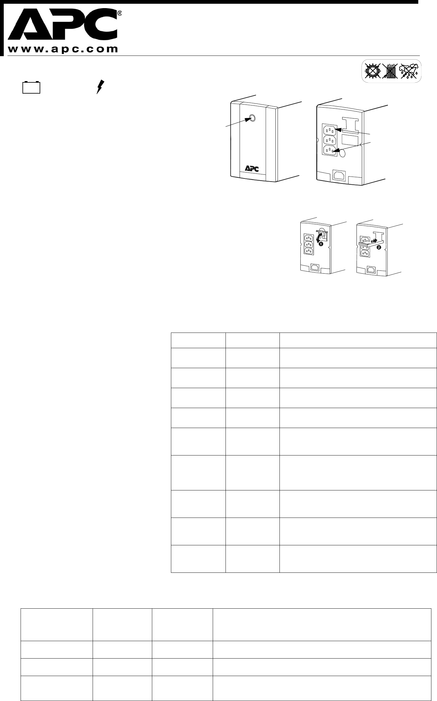
ON/OFF and
LED Status
Indicator
Battery backup and
surge protected outlets
2
3
990-3333B-005 © 2009 American Power Conversion Corp.
All other trademarks are property of their respective owners.
APC, Back-UPS and PowerChute are registered trademarks of American Power Conversion Corp.
Connect the Battery and Turn on the Unit
Connect the battery to the UPS before use. To connect the battery:
Pull the top of the battery connector lever out of the unit, until the lever is horizontal.
Push the battery connector lever completely into the unit, until the end of the lever is flush with the rear panel.
Press ON/OFF to turn on the unit.
A single short beep, and the green “Power On” indicator confirms that the Back-UPS is on and ready to provide
protection.
The Back-UPS should charge for at least 10 hours to ensure sufficient runtime. The unit is being charged
whenever it is connected to utility power, whether the unit is turned ON or OFF.
Status Indicators
The Back-UPS indicates its operating status using a combination of visual and audible indicators.
Power On LED Buzzer Condition
On Off On-line - Back-UPS is supplying conditioned utility power
to the connected equipment
On (Off during 4
beeps)
4 beeps repeated
every 30 seconds
On-Battery - Back-UPS is supplying battery power
Flashing Rapid Beeping
(every 1/2 second)
Low Battery Warning - The Back-UPS has 1.5 minutes of
remaining battery power
Flashing Constant tone Bad Battery Detected - Battery needs to be charged, or is
at end of life. (See Battery Replacement.)
Off Short beep every
4 seconds
Low Battery Shutdown - During On Battery operation the
battery power was almost completely exhausted, and the
Back-UPS is waiting for utility power to return to normal
Off Constant Tone On Battery Overload - Connected equipment requires
more power than provided by the Back-UPS battery.
Unplug devices one at a time to remove overload, if not
corrected Contact APC Technical Support
On Constant Tone On Line Overload - The power drawn by the connected
equipment exceeds the power capacity of the Battery
Backup
Flashing Chirp every 2
seconds
Charger Warning -Back-UPS has experienced an internal
problem, but continues to power the load. Contact APC
Technical Support
Off Constant Tone Charger Fault - Back-UPS has an internal problem, and is
no longer powering the load. Contact APC Technical
Support
Adjusting Transfer
Voltage and Sensitivity
Settings
Automatic Voltage Regulation boosts the utility voltage
when it drops below safe levels. This allows the
equipment plugged into the unit to operate during low
voltage conditions, conserving the battery power in the
event of a power outage.
The Back-UPS will switch to battery power if the input
voltage level becomes too low for the Automatic
Voltage Regulation to compensate, or if the utility
power is distorted.
If the Back-UPS switches to battery power too
frequently or too infrequently, adjust the transfer
voltage and sensitivity settings:
1. Ensure the Back-UPS is off. Plug it into utility
power.
2. Press and hold ON/OFF until the LED repeatedly
flashes. The unit is now in Program Mode.
3. Release the button. The LED will flash once,
twice, or three times per second, indicating the
current setting. See Transfer Voltage and
Sensitivity Settings.
4. Press ON/OFF within two seconds to change the
setting. Each time the button is pressed, the LED
will flash at a different rate: once, twice, or three
times per second, indicating the new setting.
Continue pressing the button until the desired
setting is reached. If the button is not pressed
within five seconds, the Back-UPS will exit the
Program Mode.
5. To exit Program Mode, release the button and
wait for the LED to stop flashing.
Connect Equipment
Battery Backup Surge Protection
These outlets are powered whenever the Back-UPS is switched
ON. During a power outage, or other utility problems (brownouts,
over-voltages), these outlets will be powered for a limited time by
the Back-UPS. Plug the computer and monitor into these two
outlets.
Connect AC Power Cord
Plug the Back-UPS power cord into a wall outlet, not a surge
protector or power strip. The outlet should be near the equipment
and easily accessible.
Back-UPS
®
RS 500
BR500CI-AS User Guide
Transfer Voltage and Sensitivity Settings
LED Flashing
Transfer Voltage
Setting
Input Voltage
Range
(For Utility
Operation)
Usage
Once per second Low 155 - 280 The Back-UPS will switch to battery power less often. Use with equipment that is not
sensitive to low or high level voltage levels or minor voltage waveform distortions.
Twice per second Medium
(factory default)
160 -280 Default, use in normal conditions.
Three times per second
High 165 - 270 The Back-UPS will switch to battery power during any small fluctuation in voltage.
Use with equipment that is sensitive to low or high level voltage levels or minor
voltage waveform distortions.
bu053a


