12 User Guide Silcon DP300E Series 480V 120-160kVA
7OA0003 US rev. 03
DP300E
DP300E
Q010a
Q001a
Q002a
Q004
Q010b
Q001b Q002b
Utility 1
Q003
Service bypass switch
H003
Load
Utility 2
H004
H002b
H002a
H010a
H010b
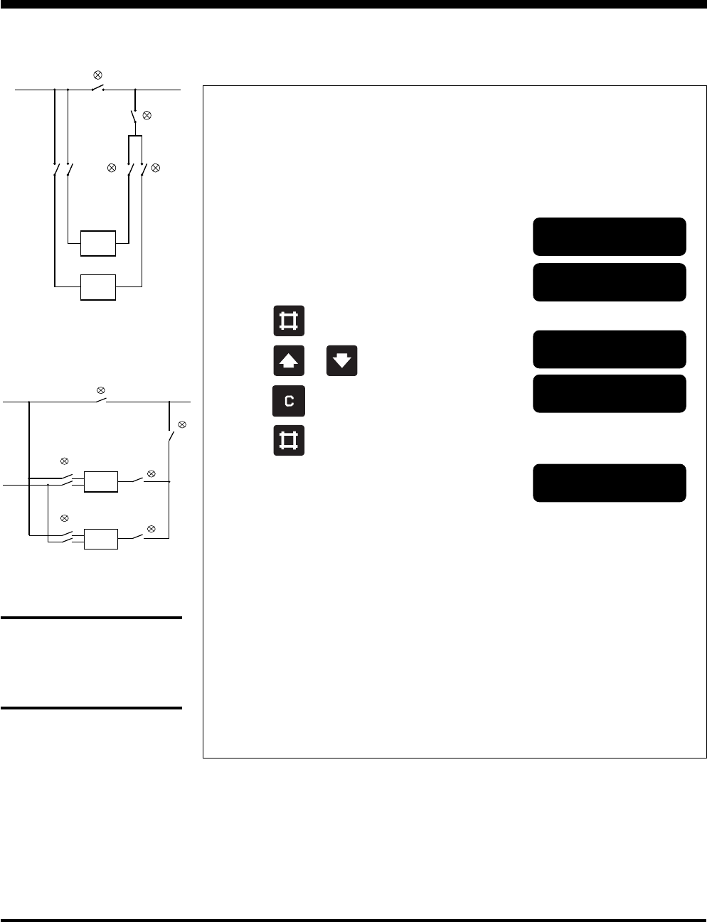
Single Utility
Dual Utility
2.7.2 Switching the parallel system from external bypass into normal
UPS operation
Action
1. Check that the output switch (Q004) is in
position “0”
2. Check that all output switches (Q002) are
in position “1”
3. Turn input switches (Q001) to position “1”
4. On systems with dual utility, turn bypass
input switches (Q010) to position “1”
5. Wait 10 sec. Open the UPS front door and press
the green “ON” push-button on all systems
6. Press
on the keyboard
7. Press or on the keyboard until
8. Press on the keyboard
9. Press
on the keyboard
All systems will transfer to bypass operation
NOTE:
if Q002‘s are off “0“ only programmed systems
goes to bypass H002 & H004 lights
10. Turn the output switch (Q004) to position “1” The green lamp (H003)
above the bypass switch
also lights.
11. Turn the bypass switch (Q003) to position “0” The green lamps (H002) and
(H004) do not light any longer,
but (H003) will light until
normal operation.
Display shows
Lamp indication
on bypass panel
Stop, Start & Operating the External Service Bypass Panel
NOTE:
If battery has been discon-
nected please refer to
“Starting Up” in Chapter 2.5.1 to
connect battery(-ies) again.
**System OFF**
Normal operation
load power 0%
Bypass operation
: NO
Bypass operation
: YES
Bypass operation
DP300E
DP300E
Q003
Service
bypass
switch
H003
Q001a
Q001b
Q002b
Q004
Q002a
LoadUtility
H004
H002aH002b


