


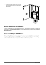
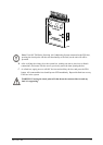


Cascade the Auxiliary Device with Wire Pairs
1. After wires are run from auxiliary device (1)
to terminal block position 9, run a second set
of wires (2) from terminal block position 9 on
the rst EPO box to terminal block position 9
on the second EPO box.
2. Continue until all boxes are connected. (See
the diagram in “Cascade Multiple EPO
Boxes“ for reference.)
1
2
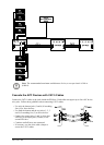
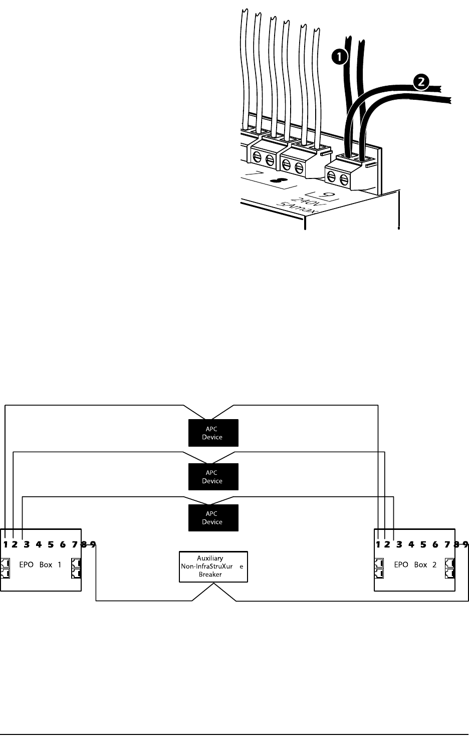
Direct Wiring Alternative
If the APC devices are centrally located between exit doors, it may be more practical to run separate wire
pairs from the devices to each EPO box. This wiring method requires terminal block connections in every
EPO box, rather than cascading cables between boxes. Connect wire pairs from the Normally Open (NO)
contacts on the devices to each EPO box. Because this alternative results in multiple wire pairs at the
terminals of the devices, APC does not recommend using it with more than three EPO boxes.
Auxiliary
Non-InfraStruXur e
Breaker
Device
Device
Device
EPO Box 1 EPO Box 2
APC
APC
APC
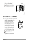
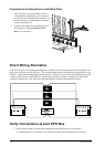
Verify Connections at each EPO Box
1. Verify that the wiring is correct before attaching critical load devices to your devices:
A. With the devices powered ON, use a small tool to press each check point, one at a time.
12
Emergency Power Off System Installation and Operation
990–1611C-001