


Revision B MX28B-1200 PRODUCT MANUAL
MX28B-1200/2400 41
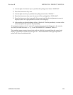
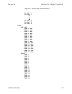
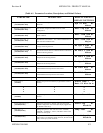
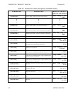
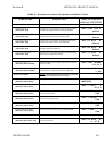
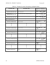
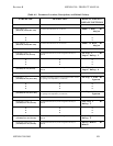
(Table 6-1. Parameter Locations, Descriptions, and Default Values)
PARAMETER DESCRIPTION DISPLAY SCREENS /
DEFAULT SETTINGS
System Low Temperature {1}
[SYSTEM/SET-ALM]
The control unit temperature is below the low temperature
threshold.
Sys LT Alm m+
Minor
Rectifier Configuration {1}
[SYSTEM/SET-ALM]
The rectifier configuration differs from its stored
configuration.
Rect Cfg Alm m+
Minor
Rectifier Fail 1-of-N {1}
[SYSTEM/SET-ALM]
Rectifier Fail 1-of-N alarm - one rectifier has at least one
alarm condition.
Rect 1ofN Alm m+
Minor
Rectifier Fail 2-of-N {1}
[SYSTEM/SET-ALM]
Rectifier Fail 2-of-N alarm – two or more rectifiers have at
least one alarm condition each.
Rect 2ofN Alm m+
Major
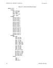
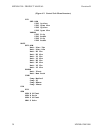
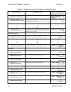
Hardware System Voltage {2}
[SYSTEM/SET-ALM]
This alarm indicates there is a hardware failure in the system
voltage monitoring function.
Hw Sys V Alm m+
Minor
Hardware Battery Current {2}
[SYSTEM/SET-ALM]
This alarm indicates there is a hardware failure in the battery
current monitoring function.
Hw Batt C Alm m+
Minor
Hardware Battery Temperature {2}
[SYSTEM/SET-ALM]
This alarm indicates there is a hardware failure in the battery
temperature monitoring function.
Hw Batt T Alm m+
Minor
Hardware System Temperature {2}
[SYSTEM/SET-ALM]
This alarm indicates there is a hardware failure in the system
temperature monitoring function.
Hw Sys T Alm m+
Minor
Hardware LVD1 {2}
[SYSTEM/SET-ALM]
This alarm indicates there is a conflict between the
commanded and sensed positions of the LVD1.
Hw LVD1 Alm m+
Minor
Hardware LVD2 {2}
[SYSTEM/SET-ALM]
This alarm indicates there is a conflict between the
commanded and sensed positions of the LVD2.
Hw LVD2 Alm m+
Minor
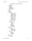
SYSTEM ALARMS DISPLAY
Alarms Item 1
[ALARMS]
Display of up to 16 active alarms (a typical alarm screen is
shown).
Alarm Item 1 +
Batt LV Alm On m
•
•
•
•
•
•
•
•
•
Alarms Item 16
[ALARMS]
Display of up to 16 active alarms (a typical alarm screen is
shown).
Alarm Item 16 +
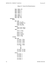
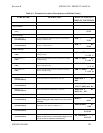
SYSTEM DIAGNOSTICS
Store Configuration {1}
[SYSTEM/DIAG]
Setting this parameter to “Enable” will cause the current
rectifier configuration to be stored (the display toggles back
to “Disable” after entry).
Store Cfg m+
Disable
Lamp Test {1}
[SYSTEM/DIAG]
Setting Lamp Test to “ON” will turn on the “MAJOR”,
“MINOR”, “NORMAL”, “MAJ”, and “MIN” LEDs on the
control unit front panel.
Lamp Test m+
OFF
Test Relay Enable {1}
[SYSTEM/DIAG]
This parameter must be set to “Enable” to permit the eight
output relays to be manually tested; otherwise, the state of the
relays will be per system conditions.
Test Relay En m+
Disable