


990-0253A, Revision 2 6/99 6
Supported Configurations
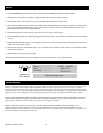
Two supported connection configurations for Redundant Switch are illustrated below. For detailed information on these
configurations and other supported configurations, please visit the APC Website at http://www.apcc.com.
Notes:
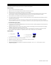
• Redundant Switch does not support communications with accessories installed in the UPS, except for SNMP accessories.
Install any other accessory you need in Redundant Switch.
• Both UPS units should be the same sine-wave model.
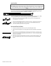
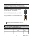
Better Configuration: Smart-UPS Redundant Switch with two Smart-UPS units connected
to one AC line.
This configuration is the minimal acceptable, since both UPS units depend on one facility power source.
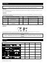
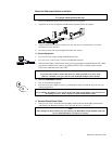
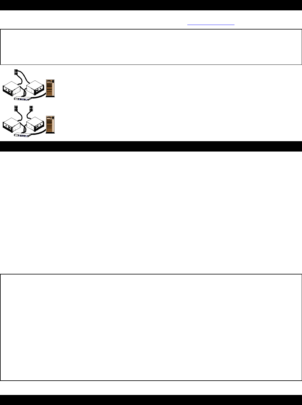
Best Configuration: Smart-UPS Redundant Switch with two Smart-UPS units connected
to two separate AC lines.
This configuration is better than the previous, since each UPS unit receives power from a separate facility
power source.
PowerChute® plus Configuration Procedure
1. Install PowerChute® plus following the instructions in the enclosed Software Installation Instruction Sheet.
2. At the Redundant Switch front panel, set the Source Preference to Source B.
3. Start the computer on which PowerChute® plus is installed.
4. Start PowerChute® plus. Communication is to UPS-B.
5. Configure UPS-B according to your requirements.
6. Set the UPSID to UPS_B.
7. At the Redundant Switch front panel, set the Source Preference to Source A.
8. Restart the computer on which PowerChute® plus is installed.
9. Start up PowerChute® plus. By default, communication is to UPS-A.
10. Configure UPS-A according to your requirements.
11. Set the UPSID to UPS_A.
Notes:
High availability is the condition in which both UPSs are available to supply AC power. Standard availability is when only
one UPS is fully available for back up power.
The following events result in a “self test failed: invalid test” message from PowerChute which indicates a change from high
availability to standard availability:
⇒ Self-test fails
⇒ Alternate UPS communication is lost
⇒ Alternate UPS voltage is out of range
⇒ UPS-A fails, Redundant Switch senses this and transfers the load’s AC power input and PowerChute communication to
UPS-B.
When the selected UPS self-tests, Redundant Switch switches to the other UPS, causing a self-test of that UPS, then switches
back.
Storage
Store the Redundant Switch covered and upright in a cool, dry location at -15 to +50 °C (+5 to +122 °F).