


990-0253A, Revision 2 6/997
Operating Instructions
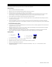
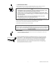
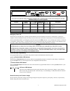
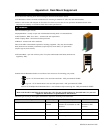
Front View
EPO
Emergency
Power Off
R
T
N
I
N
+
2
4
Function
Status Select
Status Select
To UPS B
AC Source
To UPS A
B
A
Level
Source selected
Bright
Source OK, but not selected
Dim
Source not OKOff
To Server
Redundant Switch
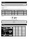
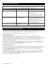
Note:
Only the Factory Default settings shown below should be used. Check that these are the current settings for your unit.
Additional setting are for future upgrades.
Function Factory User Selectable Choices Description
Default LED Bright LED Dim LED Off
Source A Sensitivity Reduced Normal Reduced Low Sets transfer sensitivity to line
conditions
Source B Sensitivity Reduced Normal Reduced Low Sets transfer sensitivity to line
conditions
Source Preference Source A Source A Source B None Selects the preferred AC source
Source A Xfer Voltage Medium Narrow Medium Wide Sets the transfer voltage window
Source B Xfer Voltage Medium Narrow Medium Wide Sets the transfer voltage window
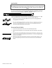
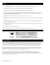
Emergency Power Off
The UPS may be switched off by a remotely operated Emergency Power Off (EPO) control. Such a configuration is common in
computer rooms and laboratories where, for safety reasons, power to the loads must be disconnected. To connect Redundant Switch
and its attached Smart-UPS to your emergency power off system, use the EPO connector. Use a normally-open contact to connect the
+24 terminal to the IN terminal. A certified electrician can wire the external blue four-pin female connector to the emergency power
off system. If this is done, and the emergency power off system is activated, neither UPS will go on-battery.
Cautions
The EPO interface is a Safety Extra Low Voltage (SELV) circuit and may be connected only to other SELV circuits.
The EPO interface is designed to monitor circuits that have no determined voltage potential. Such closure circuits may be
provided by a switch or relay properly isolated from the utility. Connection of the EPO interface to any circuit other than a
closure type circuit may cause damage to the Redundant Switch.
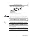
Front Panel User Programming
User programmable settings are accessible using controls located on the Redundant Switch front panel.
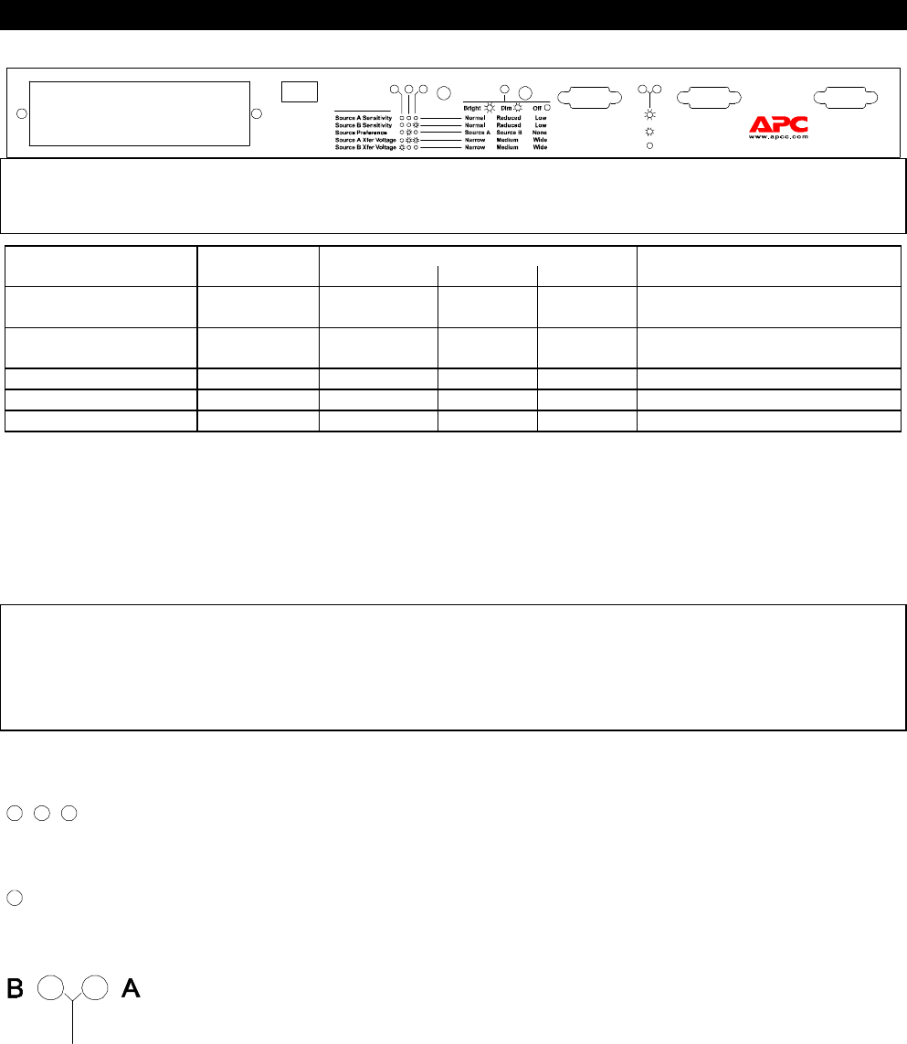
Function Select LED Indicator
The three green Function Select LEDs indicate which user programmable parameter is selected for status display or modification.
Use the left Select button to cycle through the five user configurable items listed above.
Function Status LED Indicator
The green Function Status LED indicates the state of the selected user programmable function. Use the right Select button to cycle
among the choices.
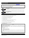
AC Source LED Indicator
The green on-line LED indicates the line quality and select status of each source: Bright = source selected;
Dim = source okay, not selected; Off = source not okay; 1 second flashing of 1 LED, other LED off = both AC
sources are out of tolerance.
Source Sensitivity and Transfer Voltage
Source sensitivity and transfer voltage can be changed using the front panel to adjust for power quality. However, only the factory
default settings shown above should be used.