


990-0253A, Revision 2 6/993
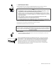
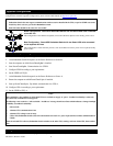
1. Install Redundant Switch.
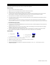
• Before plugging in the unit, install any compatible SmartSlot accessory (check our website at
www.apcc.com). Follow the installation instructions that come with the accessory.
Notes:
1. This Redundant Switch is equipped with a SmartSlot for additional manageability. See the
APC Website (www.apcc.com) for information on plug-in accessories.
2. SNMP accessories are currently unsupported in the Redundant Switch SmartSlot. Manage
the preferred Smart-UPS via SNMP by plugging the Web/SNMP Management Card into the
Smart-UPS SmartSlot.
3. Other compatible Accessories must be put into the Redundant Switch, not the UPS.
4. The Redundant Switch inlets are the main disconnect devices.
5. For multiple SmartSlot accessory configurations, please visit our Website (www.apcc.com).
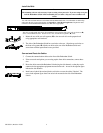
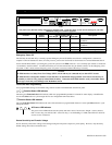
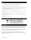
• Follow the installation instructions in the UPS’s User’s Manual to install the UPS.
• Plug the power cords attached to the Redundant Switch into each UPS.
• Both UPS units should be the same sine-wave model.
Note:
Ears and 1U rails for rack mounting the Redundant Switch (into a four-post rack) are included with
the unit. Follow the instructions below to mount the Redundant Switch, and route the cables for
maximum accessibility.
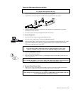
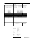
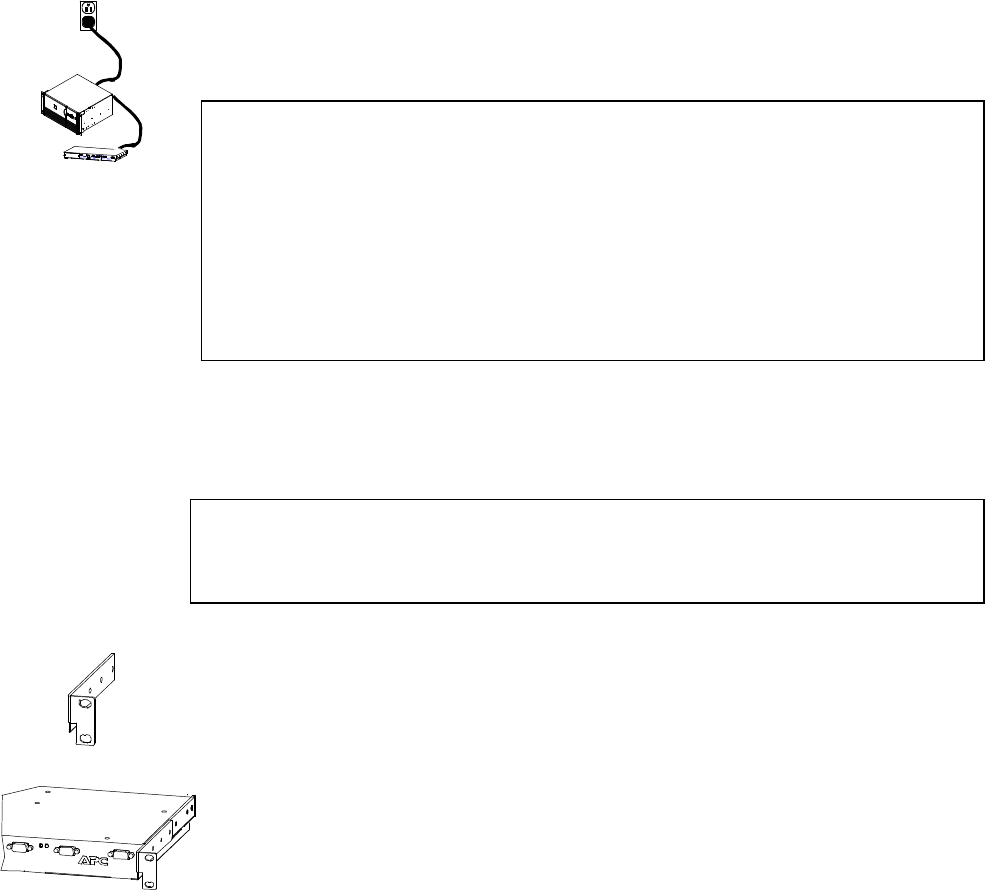
Mount the Ears
1. Two ears are available for the Redundant Switch. Each ear has four mounting holes, as shown to the
left (the ear itself hides the front hole).
2. The sides of the Redundant Switch have four matching holes at the front. To leave room to route the
cables and place the connectors flush with the front of the rack, align the second hole from the front of
each ear, shown at Œ, above, with the front hole in the corresponding side of the Redundant Switch.
(This may varyalign the two holes that best meet your needs.) Secure the ear to the Redundant
Switch with the provided screws. The ears should then be forward of the front of the Redundant
Switch and at right angles away from it, so that they can be attached to the rack. The adjacent figure
shows a Redundant Switch with the ears mounted.
Œ
Œ
•