


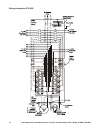
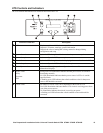
Site Preparation & Installation Guide Universal Transfer Switch UTS6 UTS6H UTS6BI UTS10BI18
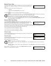
Backup2 Source Type
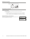
The factory default setting is UPS. The backup2 power source inlet, located on the
front of the UTS is labeled UPS Inlet as a UPS is the preferred BACKUP2 power
source.
The system setup has three options for backup power:
• Generator
• UPS (recommended BACKUP2 power source)
• Other
Use the down/up arrow keys to select the preferred backup power source.
NOTE: It is recommended that a UPS be used as BACKUP2 SOURCE TYPE. A UPS provides continuous
battery backup power during utility brownouts, sags, surges, and power outages.
Without the use of a UPS, fully automatic operation of the UTS cannot be guaranteed.
If a UPS is not selected for the BACKUP2 power source be sure that the UNINTERRUPTIBLE option under
Circuit Setup Option 2 is not selected.
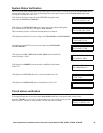
Backup2 (UPS) Power Rating
Once the BACKUP2 SOURCE TYPE has been selected, that source type will
appear in the power rating display message. Use the down/up arrow keys to set the
correct power rating for the backup2 power source connected to the UTS.
There are three levels for rapid rating increment changes. Press and hold the down or
up arrow key to adjust the power rating and to move through the three levels described here. To revert back to level 1
release the down arrow key then press and hold the down arrow key.
Level 1 increases or decreases the rating by 5 Watts.
Level 2 increases or decreases the rating by 10 Watts.
Level 3 increases or decreases the rating by 100 Watts.
Circuit 1 setup
Use the down/up arrow keys to scroll through the list of load types. Select the load
type to be supported by circuit 1.
Circuit 2 setup
Use the down/up arrow keys to scroll through the list of load types. Select the load
type to be supported by circuit 2.
Repeat this process for all of the circuits.
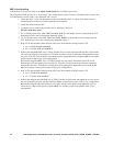
NOTE: UTS6/UTS6H - provide 120 V circuits only
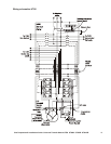
UTS6BI - together, circuits 5 and 6 form a dedicated 240 V circuit. DO NOT use these circuits as individual
120 V circuits.
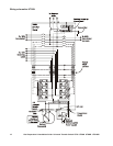
UTS10BI - Together, circuits 9 and 10 form a dedicated 240 V circuit. DO NOT use these circuits as individual
120 V circuits.
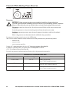
Once all of the UTS parameters have been set, the Setup Wizard ends indicating
that the UTS is setup and ready to operate.
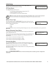
BACKUP2 SOURCE TYPE?
UPS
UPS POWER RATING?
0-1800 WATTS
CKT1 LOAD TYPE?
LIGHT
CKT1 LOAD TYPE?
LIGHT
CKT2 LOAD TYPE?
LIGHT
EXITING WIZARD
UTS IS SETUP & READY