


Installation Instructions
BEFORE YOU BEGIN INSTALLATION:
Before drilling, be sure that no cable or wiring is on the other side. Clamp all wires securely
to reduce the possibility of them being damaged during installation and use.
Keep all cables away from hot or moving parts and electrically noisy components.
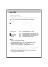
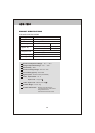
Wiring Definitions:
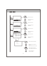
Power Connection: Pin 1 CHANNEL 1 TRIGGER -Blue
Pin 2 -
Pin 3
Pin 4 POWER IN DC (10 TO 32V) -Red
Pin 5 AUDIO/MUTE (AUDIO ON/OFF) -White
Pin 6
CHANNEL 2 TRIGGER Brown
CHANNEL 3 TRIGGER -Green
CHANNEL 4 TRIGGER -Orange
Pin 7 GROUND -Black
Pin 8 2-WAY SPLIT TRIGGER -Yellow
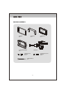
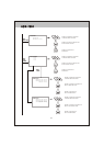
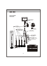
Camera 1 Input: 5-Pin Connection for tilt camera or camera
extension cable
4-Pin Connection for camera or camera extension cable
4-Pin Connection for camera or camera extension cable
4-Pin Connection for camera or camera extension cable
25-Pin D-Sub Cable connection to monitor
Camera 2 Input:
LCD Panel:
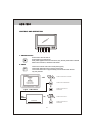
General:
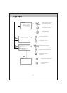
1. Choose the monitor and camera locations.
2. Install all required cables in vehicle. A 3/4" (19mm) hole should be drilled for
passing camera cables through vehicle walls, barriers, etc.
Install split grommets where applicable. If additional cable protection is
required, install convoluted tubing over the cable.
3. After cable/wiring has been routed and components are in place, temporarily make all
system connections and perform a system function check. If the system does not
operate properly, see the troubleshooting section.
10
Camera 3 Input:
Camera 4 Input:
A O M - 7 6 9 4 A O M - 7 6 9 4
4. Make sure all cables are routed away from hot or moving parts and away from
sharp edges. Secure cables with wire ties.