


9
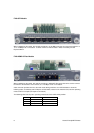
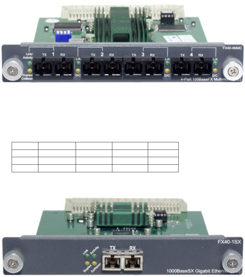
FX40-4MMC Fiber Module
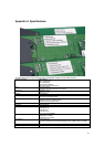
When installed into a switch, this module provides 4 x 100 Mbps Fast Ethernet fiber ports that can be used
to connect the switch to the network backbone, a 100 Mbps server or end station.
A SC connector provides the link to the multi mode fiber cabling, and there are 2 LEDs to indicate following
status: Link/Activity and Full Duplex. A DIP switch, located on the module board, sets the operating mode to
half or full duplex (full duplex is the default mode).
The following table lists the ports’ operating modes based on the DIP switch position.
Port 1 Port 2 Port 3 Port 4
SW 1 2 3 4
ON Half Duplex Half Duplex Half Duplex Half Duplex
OFF Full Duplex Full Duplex Full Duplex Full Duplex
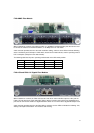
FX40-1SX and FX40-1LX Gigabit Fiber Modules
When installed into a switch, the FX40-1SX (50, 62.5/125 micron multi mode fiber optics to 2 Km) and the
FX40-1LX (8,9/125 micron single mode fiber optics to 60 Km) modules each provide one Gigabit Ethernet
port that can connect the switch to a Gigabit backbone switch or to a server with a Gigabit NIC adapter card.
A SC connector provides the link to the fiber cabling, and there are four LEDs to indicate the following: Link,
Activity, Full Duplex and Collision. The module is auto sensing.