


Chapter 3 43
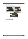
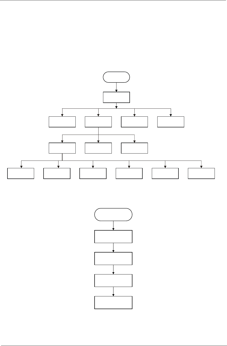
Disassembly Procedure Flowchard
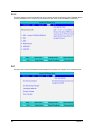
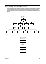
The flowchart on the succeeding page gives you a graphic representation on the entire disassembly sequence
and instructs you on the components that need to be removed during servicing. For example, if you want to
remove the system board, you must first remove the keyboard, then disassemble the inside assembly frame in
that order.
Main unit disassembly flow chart
LCM module disassembly flow chart
Start
Battery
HDD
BTCB
Memory
Thermal
module
UPPER
CASE
LCM
module
TPCB
Card reader
board
Audio
board
USB
board
Wireless
board
SSD
board
VGA
board
LCM module
LCM Mylar
LCM Bezel
LCM Panel
Start