


ASUS MEL-M User’s Manual 13
III. HARDWARE SETUP
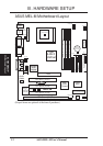
Motherboard Settings
1) KBPWR p. 14 Keyboard Power Up (Enable/Disable)
2) DIP-Switch 5 p. 15 Onboard Audio Setting
3) DIP-Switch 6 p. 15 VIO Setting
4) DIP-Switch 1,2,3,4 p. 16 CPU Bus Frequency Selection
5) DIP-Switch 7,8,9,10 p. 16 CPU Core:Bus Frequency Multiple
Expansion Slots
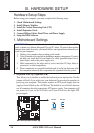
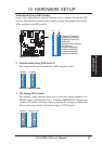
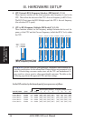
1) DIMM Sockets p. 17 168-Pin DIMM Memory Support
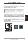
2) Socket 370 p. 19 Central Processing Unit (CPU) Socket
3) SLOT1 p. 21 16-bit ISA Bus Expansion Slots
*
4) PCI1, PCI2, PCI3 p. 22 32-bit PCI Bus Expansion Slots
5) AGP p. 22 Accelerated Graphics Port
Connectors
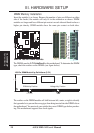
1) PS2KBMS p. 23 PS/2 Mouse Connector (6-pin female)
2) PS2KBMS p. 23 PS/2 Keyboard Connector (6-pin female)
3) USB p. 24 Universal Serial BUS Ports 1 & 2 (Two 4-pin female)
4) PRINTER p. 24 Parallel Port Connector (25-pin female)
5) COM1, COM2 p. 24 Serial Port COM1 and COM2 Connectors (9-pin male)
6) GAME_AUDIO p. 25 Joystick/Midi Connector (15-pin female) (optional)
7) GAME_AUDIO p. 25 Audio Port Connectors (Three 1/8” female) (optional)
8) ATXPWR p. 25 ATX Power Supply Connector (20 pins)
9) PRIMARY/SECONDARY IDE p. 26 Primary/Secondary IDE Connectors (Two 40-1pins)
10) FLOPPY p. 26 Floppy Disk Drive Connector (34-1pins)
11) CHA_, CPU_, PWR_FAN p. 27 Chassis, CPU, Power Supply Fan Connectors (Three 3-pin)
12) WOL_CON p. 27 Wake-On-LAN Connector (3 pins)
13) IR p. 28 IrDA-Compliant Infrared Module Connector (5 pins)
14) IDELED p. 28 IDE LED Activity Light (2 pins)
15) SBLINK p. 29 SB-Link Connector (6-1 pins)
16) CHASIS p. 29 Chassis Intrusion Sensor Lead (4-1 pins)
17) SMB p. 30 SMBus Connector (5-1 pins)
18) AUX/VIDEO_IN p. 30 Stereo Audio In Connectors (Two 4-pin)
19) CD1/CD2 p. 31 Stereo Audio In Connector (Two 4-pin)
20) MODEM p. 31 Modem Card Voice In Connector (4 pins)
21) MSG.LED (PANEL) p. 32 System Message LED (2 pins)
22) SMI (PANEL) p. 32 SMI Switch Lead (2 pins)
23) PWR.SW (PANEL) p. 32 ATX Power & Soft-Off Switch Lead (2 pins)
24) RESET (PANEL) p. 32 Reset Switch Lead (2 pins)
25)
PWR.LED (
PANEL
)
p. 32 System Power LED Lead (3-1 pins)
26)
KEYLOCK (
PANEL
)
p. 32 Keyboard Lock Switch Lead (2 pins)
27) SPEAKER (PANEL) p. 32 System Warning Speaker Connector (4 pins)
*
The onboard hardware monitor uses the address 290H-297H so legacy ISA cards
must not use this address; otherwise, conflicts will occur.
Layout Contents
III. H/W SETUP