


ASUS A7N266 User’s Manual 37
3. HARDWARE SETUP
Connectors
3. H/W SETUP
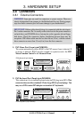
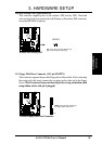
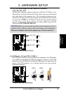
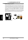
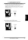
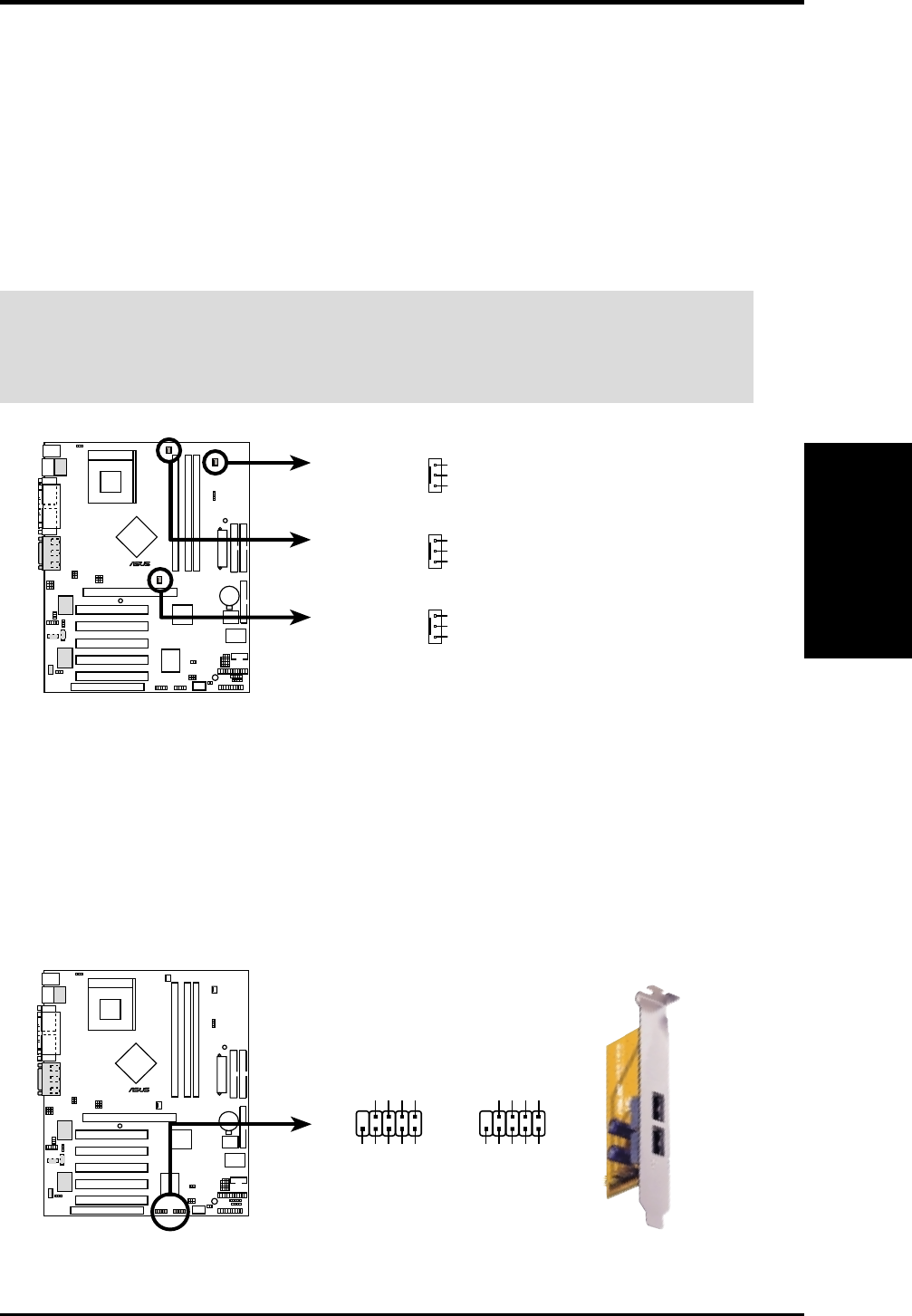
13) CPU Fan, North Bridge Fan, and Chassis Fan Connectors
(CPU, NB, CHA_FAN)
The three fan connectors support cooling fans of 350mA (4.2 Watts) or less.
Orient the fans so that the heat sink fins allow airflow to go across the onboard
heat sinks instead of the expansion slots. The fan wiring and plug may vary.
Connect the fan cable to the connector making sure that the black wire matches
the ground pin. NOTE: Use the “Rotation” signal only with a specially designed
fan with a rotation signal. Monitor Rotations Per Minute (RPM) using ASUS PC
Probe (see 6. SOFTWARE REFERENCE).
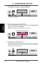
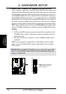
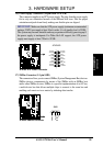
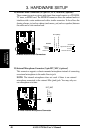
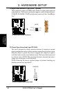
14) USB Headers (10-1 pin USB2_3, USB4_5)
If the USB port connectors on the back panel are inadequate, two USB headers
are available for four additional USB port connectors. Connect a 2-port USB
connector set to a USB header and mount the USB bracket to an open slot in the
chassis. (The USB connector set is optional and does not come with the
motherboard package.)
A7N266
010101
®
A7N266 12-Volt Cooling Fan Power
CHA_FAN
GND
Rotation
+12V
CPU_FAN
NB_FAN
GND
Rotation
+12V
GND
Rotation
+12V
A7N266
010101
®
A7N266 Front Panel USB Headers
USB23USB45
NC
GND
USBP4+
USBP4–
USB Power
GND
USBP5+
USBP5–
USB Power
15
610
15
610
NC
GND
USBP2+
USBP2–
USB Power
GND
USBP3+
USBP3–
USB Power
WARNING! Make sure to connect the fan cables to the fan connectors. Lack of
sufficient airflow within the system could cause damage to the motherboard.
These are not jumpers, do not place jumper caps over these connectors!