


42 ASUS A7N266 User’s Manual
3. HARDWARE SETUP
Connectors
3. H/W SETUP
A7N266
010101
®
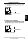
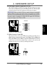
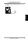
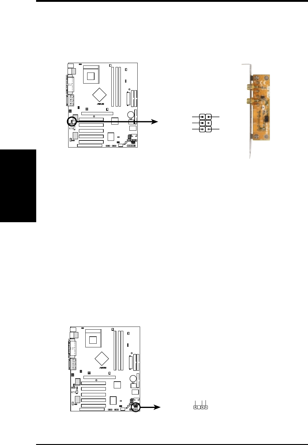
A7N266 Digital Audio Connector
SPDIF
GND
+5V
SPDIF_IN
SPDIF_OUT
GND
1
22) Digital Audio Interfaces (2-pin S/PDIF) (optional)
These connectors support an S/PDIF audio bracket for digital audio input and
output functions. The connector and bracket support a variety of digital resources:
CD-ROM, DVD-ROM, CD-RW and advanced sound cards like SoundBlaster
Live
™
.
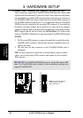
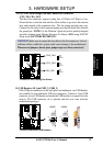
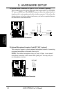
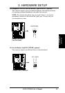
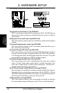
23) Chassis Open Alarm Lead (4-pin CHASSIS)
This lead is designed for chassis intrusion detection. It requires an external
detection mechanism such as a chassis intrusion monitor/sensor or microswitch.
When the chassis is opened, the sensor is triggered and a high-level signal is
sent to this lead to record a chassis intrusion event. The event is then be processed
by software such as LDCM. When not using the chassis intrusion lead, place a
jumper cap over the pins to close the circuit.
NOTE: Removing the chassis intrusion jumper cap without attaching any
detectors prevents boot-up of the PC.
A7N266
010101
®
A7N266 Chassis Open Alarm Lead
CHASSIS
+5Volt
(Power Supply Stand By)
Ground
Chassis Signal
1