


1-16
Chapter 1: Product introduction
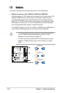
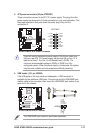
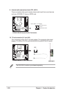
2. Floppy disk drive connector (34-1 pin FLOPPY1)
This connector supports the provided floppy drive ribbon cable. After
connecting one end to the motherboard, connect the other end to the floppy
drive. (Pin 5 is removed to prevent incorrect insertion when using cable
connectors with a closed pin 5 slot.)
A7N8X-VM
NOTE: Orient the red markings on
the floppy ribbon cable to
PIN 1
A7N8X-VM/400 Floppy Disk Drive Connector
PIN 1
FLOPPY1
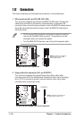
1.12 Connectors
This section describes and illustrates the connectors on the motherboard.
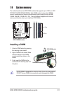
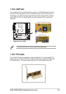
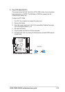
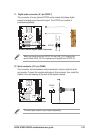
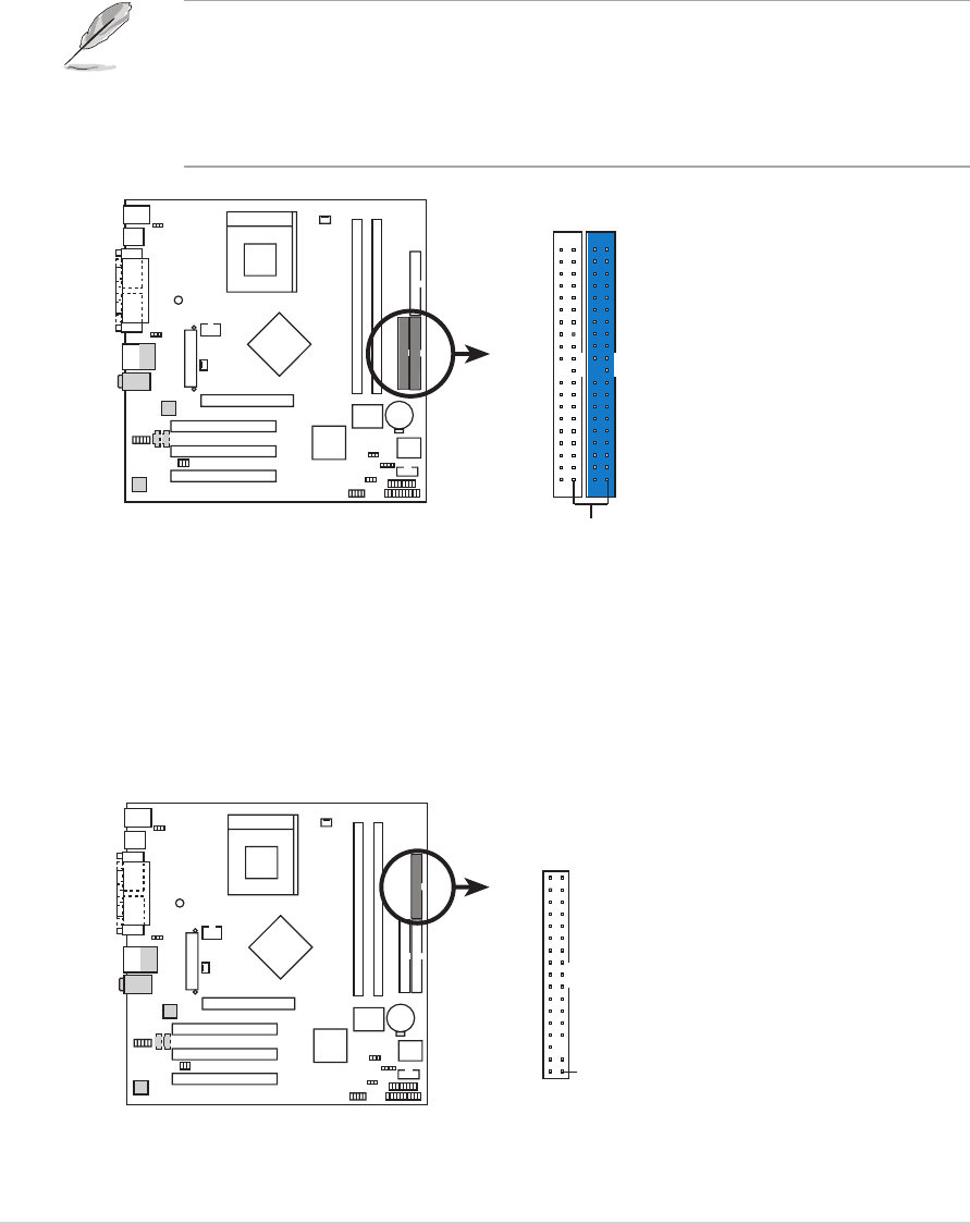
1. IDE connectors (40-1 pin PRI_IDE, SEC_IDE)
This connector supports the provided UltraDMA133 IDE cable. Connect the
cable’s blue connector to the primary (recommended) or secondary IDE
connector, then connect the gray connector to the UltraDMA133 master device
(hard disk drive) and the black connector to the UltraDMA133 slave device
(hard disk drive).
A7N8X-VM
A7N8X-VM/400 IDE Connectors
NOTE: Orient the red markings
(usually zigzag) on the IDE
ribbon cable to PIN 1.
SEC_IDE
PIN 1
PRI_IDE
• Pin 20 on each IDE connector is removed to match the covered
hole on the UltraDMA cable connector. This prevents incorrect
orientation when you connect the cables.
• For UltraDMA133 IDE devices, use a 40-pin 80-conductor cable.