


ASUS A7N8X-VM/400 motherboard user guide
1-17
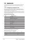
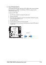
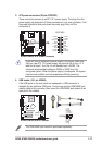
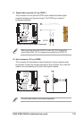
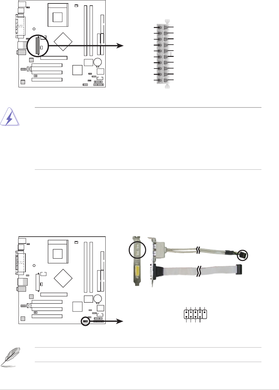
3. ATX power connectors (20-pin ATXPWR1)
These connectors connect to an ATX 12 V power supply. The plugs from the
power supply are designed to fit these connectors in only one orientation. Find
the proper orientation and push down the power plug firmly until the
connectors fit.
A7N8X-VM
A7N8X-VM/400 ATX Power Connector
ATXPWR1
+3.3VDC
-12.0VDC
COM
PS_ON#
COM
COM
COM
-5.0VDC
+5.0VDC
+5.0VDC
PWR_OK
+12.0VDC
+3.3VDC
+3.3VDC
COM
+5.0VDC
COM
+5.0VDC
COM
+5VSB
If you will need to replace the power supply in the future, make sure
that your new ATX 12 V power supply can provide 8 A on the +12 V
lead and at least 1 A on the +5-volt standby lead (+5VSB). The
minimum recommended wattage is 230W, or 300W for a fully-
configured system. When the power supply is inadequate, the system
may become unstable and may experience difficulty powering.
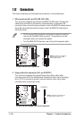
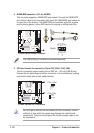
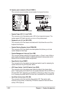
4. USB header (10-1 pin USB56)
If the USB ports on the rear panel are inadequate, a USB connector is
available for two additional USB ports. Connect one end the USB/GAME port
module cable to this connector, then mount the USB/GAME port module to an
open slot in the chassis.
A7N8X-VM
A7N8X-VM/400 USB 2.0 Header
USB56
USB+5V
USB_P6-
USB_P6+
GND
NC
USB+5V
USB_P5-
USB_P5+
GND
1
The USB/GAME port module is purchased separately.