


1-10
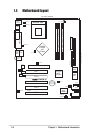
Chapter 1: Motherboard Information
1.9 Jumpers
This section describes and illustrates the jumpers on the motherboard.
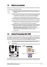
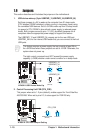
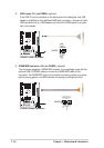
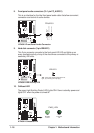
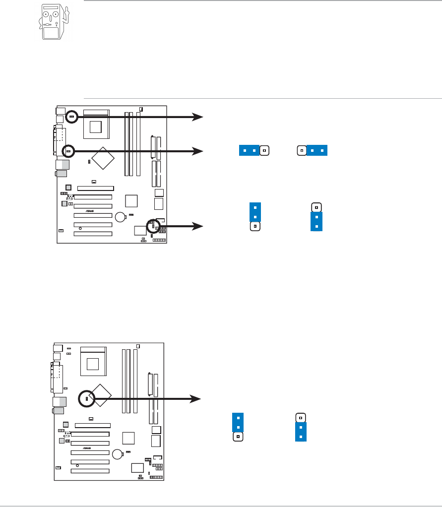
1. USB device wake-up (3-pin USBPWR_12,USBPWR_34,USBPWR_56)
Set these jumpers to +5V to wake up the computer from S1 sleep mode
(CPU stopped, DRAM refreshed, system running in low power mode) using
the connected USB devices. Set to +5VSB to wake up from S3 sleep mode
(no power to CPU, DRAM in slow refresh, power supply in reduced power
mode). Both jumpers are set to pins 1-2 (+5V) by default because not all
computers have the appropriate power supply to support this feature.
The USBPWR_12 and USBPWR_34 jumpers are for the rear USB port.
USBPWR_56 is for the internal USB header that you can connect to the front
USB ports.
This feature requires a power supply that can provide at least 2A on
the +5VSB lead when these jumpers are set to +5VSB. Otherwise, the
system does not power up.
The total current consumed must NOT exceed the power supply
capability (+5VSB) whether under normal condition or in sleep mode.
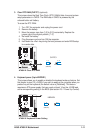
A7N8X-X
®
A7N8X-X USB Device Wake Up
USBPWR_12
USBPWR_34
USBPWR_56
(Default)
+5V
1
2
+5VSB
2
3
1
2
3
2
(Default)
+5V
+5VS
B
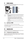
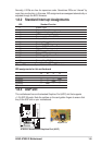
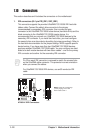
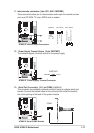
2. Central Processing Unit FSB (CPU_FSB)
This jumper when set to 1-2 pins (default), enable support for Front Side Bus
400/333/266. When set to pins 2-3, it sets support for FSB 200 only.
A7N8X-X
®
A7N8X-X CPU FSB Jumper Setting
CPU_FSB
FSB400/333/266 FSB20
0
(Default)
1
2
3
2