


1-8
Chapter 1: Product introduction
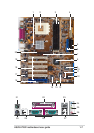
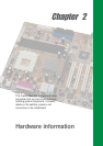
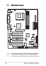
North bridge controller. The VIA
®
KT400 supports AGP 8X mode,
266/200MHz Front Side Bus, and the latest 400/333/266/200MHz
64-bit memory bus.
CPU socket. Socket 462 (Socket A) surface mount, Zero Insertion
Force (ZIF) socket for the AMD Athlon XP/Athlon/Duron
Processors, with 600 MHz ~ 2.4GHz system bus.
DDR DIMM sockets. These three 184-pin DIMM sockets support
up to 3GB system memory using unbuffered non-ECC PC3200/
2700/2100/1600 DDR DIMMs.(Note: PC2700 maximum to 2 DIMM
support only. PC3200 maximum to 1 DIMM support only.)
Visit the ASUS website (www.asus.com) for the latest qualified DDR400 module list.
ATX power connector. This 20-pin connector connects to an ATX
+12V power supply. The power supply must have at least 1A on the
+5V standby lead (+5VSB).
Floppy disk connector. This connector accommodates the
provided ribbon cable for the floppy disk drive. One side of the
connector is slotted to prevent incorrect insertion of the floppy disk
cable.
IDE connectors. These dual-channel bus master IDE connectors
support up to four Ultra DMA133/100/66, PIO Modes 3 & 4 IDE
devices. Both the primary (blue) and secondary (black) connectors
are slotted to prevent incorrect insertion of the IDE ribbon cable.
AGP warning LED. Serving as a smart burn-out protection for the
motherboard, this red LED lights up if you plug in any 3.3V AGP
card into the AGP slot. When this LED is lit, there is no way you
can turn on the system power even if you press the power button.
South bridge controller. The VIA
®
VT8235 integrated peripheral
controller supports various I/O functions including, 2-channel ATA/
133 bus master IDE controller, up to six USB 2.0 ports, LPC Super
I/O interface, AC’97 interface and PCI 2.2 interface.
ASUS ASIC. This chip performs multiple system functions that
include hardware and system voltage monitoring among others.
9
8
7
6
5
4
3
2
1
1.4.2 Core specifications