


2-28
Chapter 2: Hardware information
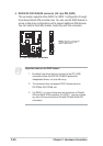
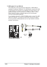
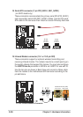
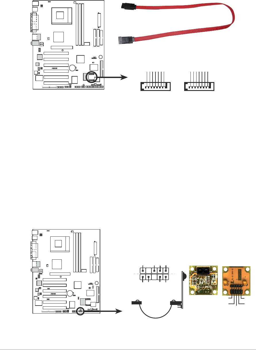
19. Infrared Module connector (10-1 or 10-2 pin SIR)
These connectors support an optional wireless transmitting and
receiving infrared module. The module mounts to a small opening on
the system chassis that support this feature. You must also configure
the UART2 Use As parameter in BIOS to set UART2 for use with IR.
Use the ten pins as shown in Back View and connect a ribbon cable
from the module to the motherboard SIR connector according to the
pin definitions.
A7V8X
®
A7V8X Infrared Module Connector
Standard Infrared (SIR)
Front View Back View
+5V
IRTX
IRRX
(NC)
GND
SIR
+5V
IRRX
IRTX
GND
IRTX
GND
CIRRX
CIR+5V
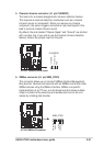
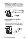
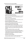
18. Serial ATA connector (7 pin PRI_SATA1, SEC_SATA1)
(on SATA model only)
These connectors accommodate the primary serial ATA (PRI_SATA1)
and a secondary serial ATA (SEC_SATA1) cables. Connect the serial
ATA cable to this connector then install to a serial ATA ready hard disk.
A7V8X
®
A7V8X SATA Connectors SEC_SATA1 PRI_SATA1
GND
RSATA_TXP1
RSATA_TXN1
GND
RSATA_RXP1
RSATA_RXN1
GND
GND
RSATA_TXP2
RSATA_TXN2
GND
RSATA_RXP2
RSATA_RXN2
GND