


2-18
Chapter 2: Hardware information
2.8 Connectors
This section describes and illustrates the internal connectors on the
motherboard.
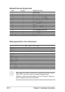
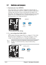
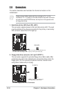
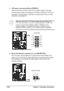
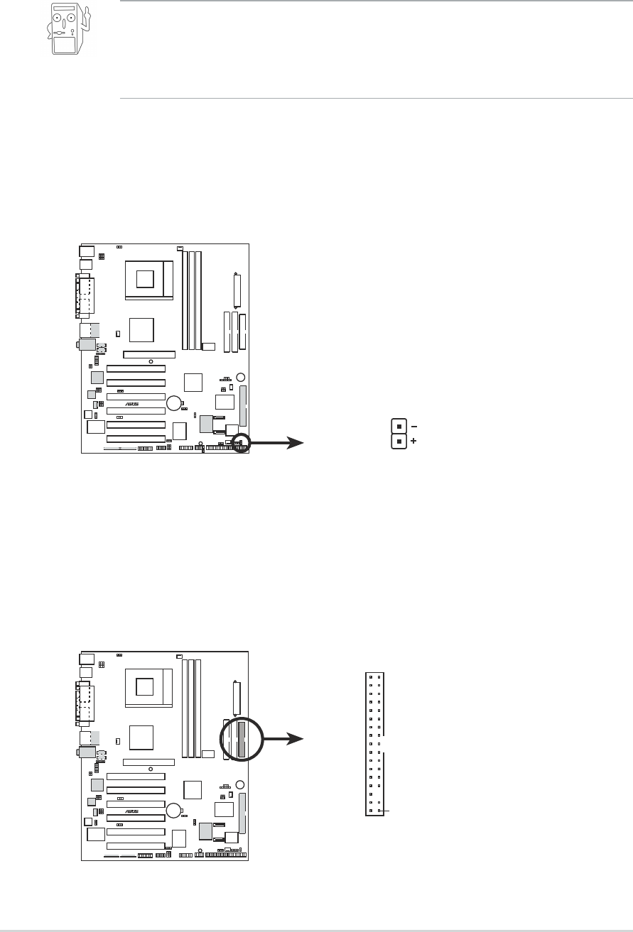
1. Hard disk activity LED (2-pin IDE_LED1)
This connector supplies power to the hard disk activity LED. The read
or write activities of any device connected to the primary or secondary
IDE connector cause this LED to light up.
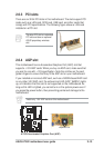
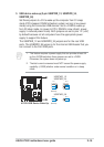
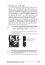
2. Floppy disk drive connector (34-1 pin FLOPPY1)
This connector supports the provided floppy drive ribbon cable. After
connecting one end to the motherboard, connect the other end to the
floppy drive. (Pin 5 is removed to prevent incorrect insertion when
using ribbon cables with pin 5 plug).
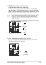
Always connect ribbon cables with the red stripe to Pin 1 on the
connectors. Pin 1 is usually on the side closest to the power connector
on hard drives and CD-ROM drives, but may be on the opposite side
on floppy disk drives.
A7V8X
®
IDELED1
A7V8X IDE Activity LED
TIP: If the case-mounted LED does not
light, try reversing the 2-pin plug.
A7V8X
®
NOTE: Orient the red markings on
the floppy ribbon cable to PIN 1.
A7V8X Floppy Disk Drive Connector
PIN 1
FLOPPY1