


1-261-26
1-261-26
1-26
Chapter 1: Product introductionChapter 1: Product introduction
Chapter 1: Product introductionChapter 1: Product introduction
Chapter 1: Product introduction
6.6.
6.6.
6.
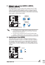
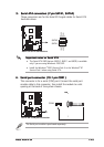
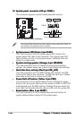
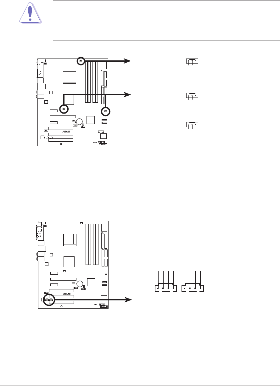
Internal audio connectors (4-pin CD, AUX)Internal audio connectors (4-pin CD, AUX)
Internal audio connectors (4-pin CD, AUX)Internal audio connectors (4-pin CD, AUX)
Internal audio connectors (4-pin CD, AUX)
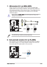
These connectors allow you to receive stereo audio input from sound
sources such as a CD-ROM, TV-tuner, or MPEG card.
A8V-E SE
®
A8V-E SE Internal audio connectors
AUX
Right Audio Channel
Left Audio Channel
Ground
Ground
CD
Right Audio Channel
Left Audio Channel
Ground
Ground
5.5.
5.5.
5.
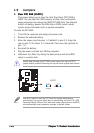
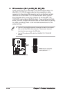
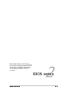
CPU, Chassis, and Power fan connectorsCPU, Chassis, and Power fan connectors
CPU, Chassis, and Power fan connectorsCPU, Chassis, and Power fan connectors
CPU, Chassis, and Power fan connectors
(3-pin CPU_FAN, 3-pin CHA_FAN1, 3-pin PWR_FAN)(3-pin CPU_FAN, 3-pin CHA_FAN1, 3-pin PWR_FAN)
(3-pin CPU_FAN, 3-pin CHA_FAN1, 3-pin PWR_FAN)(3-pin CPU_FAN, 3-pin CHA_FAN1, 3-pin PWR_FAN)
(3-pin CPU_FAN, 3-pin CHA_FAN1, 3-pin PWR_FAN)
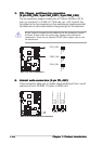
The fan connectors support cooling fans of 350mA~2000mA (24 W
max.) or a total of 1A~3.48A (41.76 W max.) at +12V. Connect the
fan cables to the fan connectors on the motherboard, making sure that
the black wire of each cable matches the ground pin of the connector.
Do not forget to connect the fan cables to the fan connectors. Lack of
sufficient air flow inside the system may damage the motherboard
components. These are not jumpers! DO NOT place jumper caps on the
fan connectors!
A8V-E SE
®
A8V-E SE Fan connectors
CPU_FAN
CHA_FAN
PWR_FAN
GND
Rotation
+12V
GND
Rotation
+12V
GND
Rotation
+12V