


ASUS AM1I-A
1-19
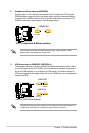
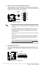
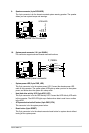
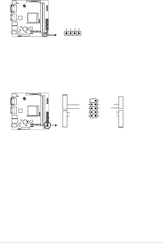
10. System panel connector (10-1 pin PANEL)
This connector supports several chassis-mounted functions.
PIN 1
PWR BTN
GND
PWR
PWR_LED-
PWR_LED+
(NC)
HWRST#
Ground
HDD_LED-
HDD_LED+
F_PANEL
+PWR LED
+HDD_LED RESET
AM1I-A
AM1I-A System panel connector
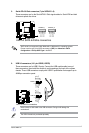
• System power LED (2-pin PWR_LED)
This 2-pin connector is for the system power LED. Connect the chassis power LED
cable to this connector. The system power LED lights up when you turn on the system
power, and blinks when the system is in sleep mode.
• Hard disk drive activity LED (2-pin HDD_LED)
This 2-pin connector is for the HDD Activity LED. Connect the HDD Activity LED cable
to this connector. The HDD LED lights up or ashes when data is read from or written
to the HDD.
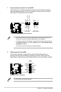
• ATX power button/soft-off button (2-pin PWR_BTN)
This connector is for the system power button.
• Reset button (2-pin RESET)
This 2-pin connector is for the chassis-mounted reset button for system reboot without
turning off the system power.
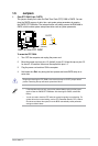
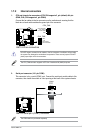
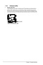
9. Speaker connector (4-pin SPEAKER)
The 4-pin connector is for the chassis-mounted system warning speaker. The speaker
allows you hear system beeps and warnings.
AM1I-A
AM1I-A Speaker Out Connector
+5V
GND
GND
Speaker Out
SPEAKER
PIN 1