


ASUS CRW-2410S User’s Manual
13
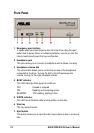
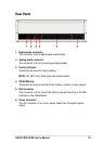
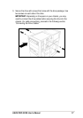
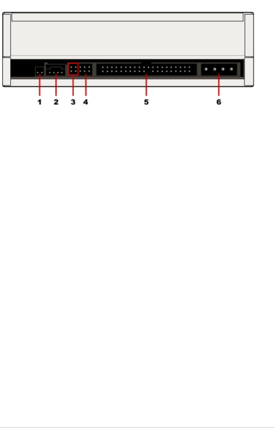
Rear Panel
1. Digital audio connector
This connector is for a digital signal output cable.
2. Analog audio connector
This connector is for an analog signal output cable.
3. Factory test pins
These pins are used for factory testing.
NOTE:
DO NOT cover these pins with jumper blocks.
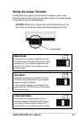
4. CS/SL/MA pins
These pins are used to set the drive to either a master or slave device.
5. IDE connector
This connector is for a 40-pin IDE cable to connect the drive to the IDE
interface on the motherboard.
6. Power connector
This DC connector is for a 4-pin power cable from the system power
supply.