


1-28 Chapter 1: Product introduction
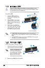
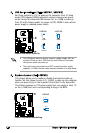
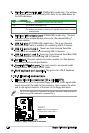
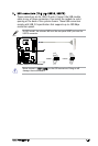
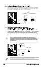
8. Wireless LAN antenna port (P5NSLI/WiFi model only). This port
connects to the optional dipolar antenna for the onboard WiFi-g™
wireless solution.
9. USB 2.0 port 7 (P5NSLI/WiFi model only). This 4-pin Universal
Serial Bus (USB) ports is available for connecting USB 2.0 devices.
10. USB 2.0 ports 3 and 4. These two 4-pin Universal Serial Bus
(USB) ports are available for connecting USB 2.0 devices.
11. USB 2.0 ports 1 and 2. These two 4-pin Universal Serial Bus (USB)
ports are available for connecting USB 2.0 devices.
12. Serial port. This port connects a mouse, modem, or other devices
that conform with serial specication.
13. Coaxial S/PDIF Out port. This port connects an external audio
output device via a coaxial S/PDIF cable.
14. PS/2 keyboard port (purple). This port is for a PS/2 keyboard.
1.10.2 Internal connectors
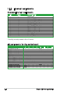
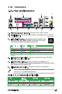
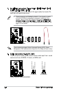
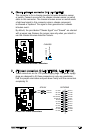
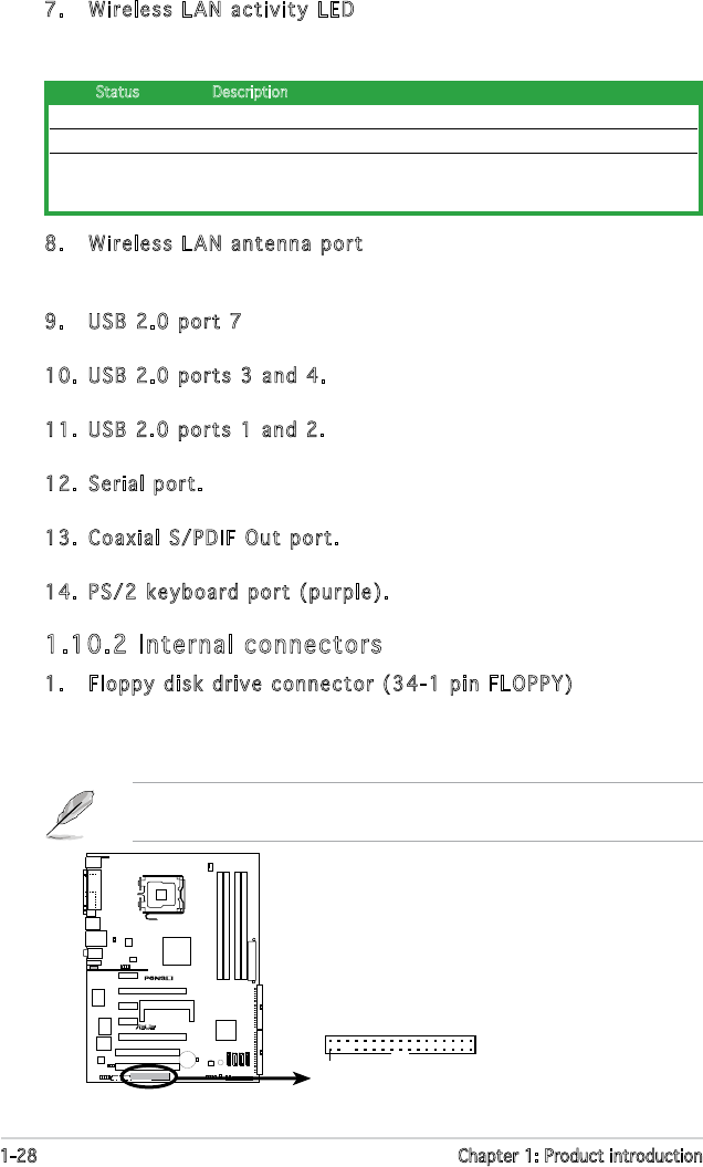
1. Floppy disk drive connector (34-1 pin FLOPPY)
This connector is for the provided oppy disk drive (FDD) signal cable.
Insert one end of the cable to this connector, then connect the other
end to the signal connector at the back of the oppy disk drive.
Pin 5 on the connector is removed to prevent incorrect cable connection
when using a FDD cable with a covered Pin 5.
R
FLOPPY
NOTE: Orient the red markings on
the floppy ribbon cable to PIN 1.
PIN 1
P5NSLI Floppy Disk Drive Connector
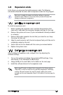
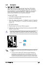
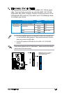
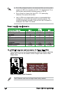
7. Wireless LAN activity LED (P5NSLI/WiFi model only). The wireless
LAN module comes with an activity LED. Refer to the table below for
the LED indications.
ON The wireless LAN module is on but has no data activity
OFF The wireless LAN module is off
Flashing The wireless LAN module is transmitting or receiving data or both.
The wireless LAN module is scanning for available access point or another
wireless device
Status Description