ASUS Commando 2-29
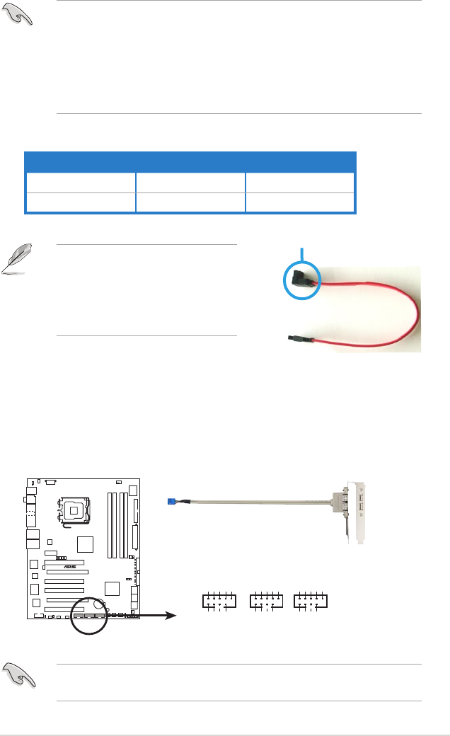
Connect the right-angle side of SATA
signal cable to the SATA device, or
connect the right-angle side of the
SATA cable to the onboard SATA port
to avoid mechanical conict with huge
graphics cards.
4. USB connectors (10-1 pin USB56, USB78, USB910)
These connectors are for USB 2.0 ports. Connect the USB module cable
to any of these connectors, then install the module to a slot opening at the
back of the system chassis. These USB connectors comply with USB 2.0
specication that supports up to 480 Mbps connection speed.
You can connect the USB cable to ASUS Q-Connector (USB, blue) rst, and
then install the Q-Connector (USB) to the USB connector onboard.
®
COMMANDO
COMMANDO USB 2.0 connectors
USB56
NC
GND
USB_P6+
USB_P6-
USB+5V
GND
USB_P5+
USB_P5-
USB+5V
1
USB78
NC
GND
USB_P8+
USB_P8-
USB+5V
GND
USB_P7+
USB_P7-
USB+5V
1
USB910
NC
GND
USB_P10+
USB_P10-
USB+5V
GND
USB_P9+
USB_P9-
USB+5V
1
•
You must install Windows
®
2000 Service Pack 4 or the Windows
®
XP
Service Pack 1 before using Serial ATA hard disk drives. The Serial ATA
RAID feature (RAID 0/RAID 1/RAID 5/RAID 10) is available only if you are
using Windows
®
2000/XP or later version.
•
When using the connectors in Standard IDE mode, connect the primary
(boot) hard disk drive to the SATA1/2/5/6 connector. Refer to the table
below for the recommended SATA hard disk drive connections.
Serial ATA hard disk drive connection
right angle side
Connector Setting Use
SATA 1/2/5/6 Master Boot disk
SATA 3/4 Slave Data disk


