


ASUS F2A85-M2
1-7
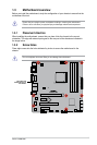
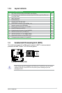
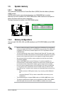
1.3.4 Layout contents
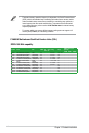
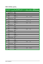
Connectors/Jumpers/Slots/LED Page
1. ATX power connectors (24-pin EATXPWR, 4-pin ATX12V) 1-26
2. CPU, power fan and chassis fan connectors (4-pin CPU_FAN, 4-pin CHA_FAN1 and
4-pin CHA_FAN2)
1-27
3. AMD
®
FM2 Socket 1-7
4. DDR3 DIMM slots 1-11
5. Standby power LED (SB_PWR) 1-31
6. SATA 6.0Gb/s connectors (7-pin SATA6G_1~6) 1-29
7. Speaker connector (4-pin SPEAKER) 1-26
8. System panel connector (10-1 pin F_PANEL) 1-30
9. Clear RTC RAM (3-pin CLRTC) 1-22
10. Chassis intrusion connector (4-1 pin CHASSIS) 1-27
11. USB 3.0 connector (20-1 pin USB3_34) 1-28
12. USB 2.0 connectors (10-1 pin USB56, USB78) 1-28
13. Digital audio connector (4-1 pin SPDIF_OUT) 1-25
14. Front panel audio connector (10-1 pin AAFP) 1-25
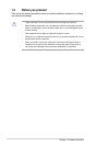
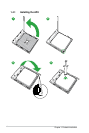
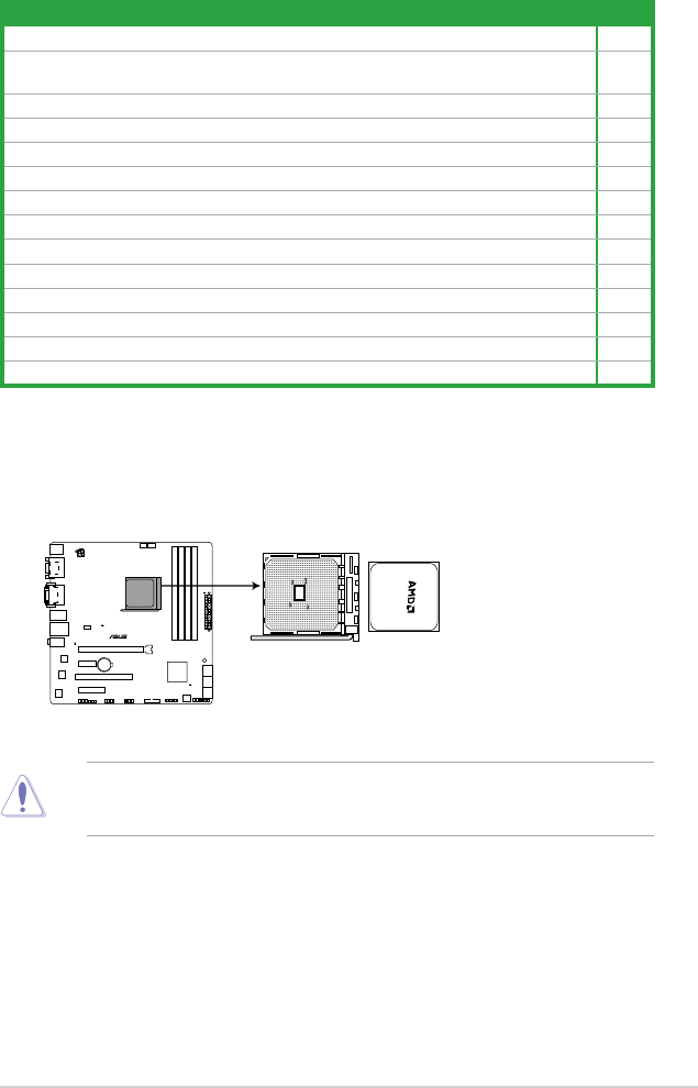
1.4 Accelerated Processing Unit (APU)
This motherboard comes with an FM2 socket designed for AMD
®
A- series accelerated
processors with AMD
®
Radeon™ HD 7000 series graphics.
Ensure that you use a APU designed for the FM2 socket. The APU ts in only one correct
orientation. DO NOT force the APU into the socket to prevent bending the pins and
damaging the APU!
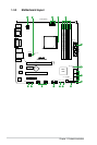
F2A85-M2
F2A85-M2 CPU socket FM2