


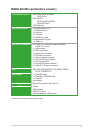
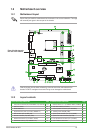
1.2 Motherboard overview
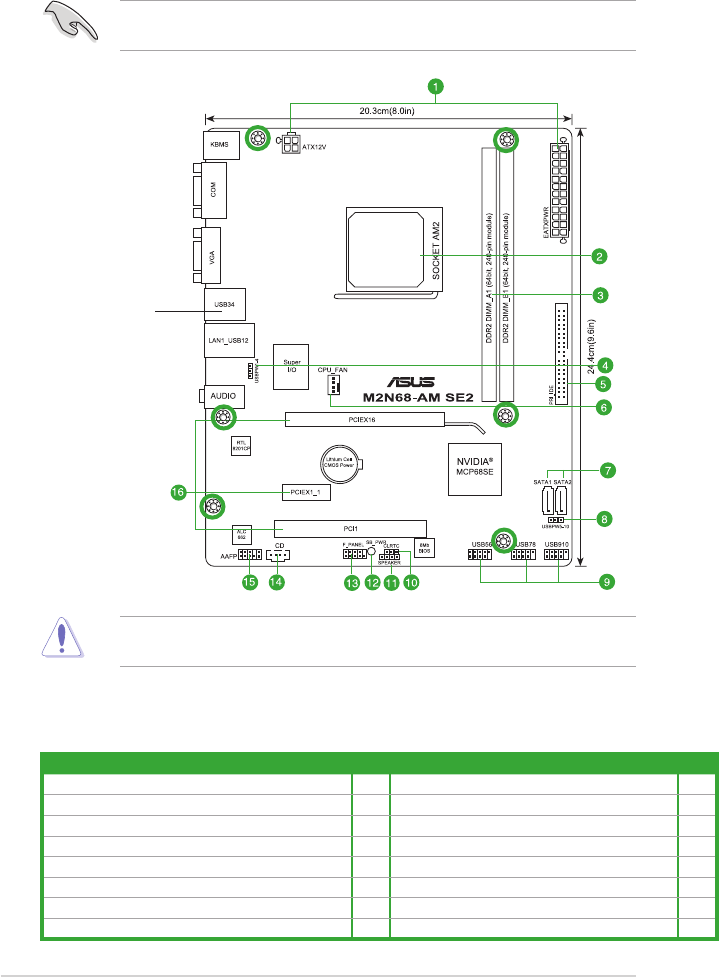
1.2.1 Motherboard layout
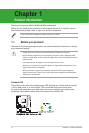
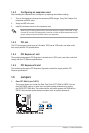
Place six screws into the holes indicated by circles to secure the motherboard to the
chassis. DO NOT overtighten the screws! Doing so can damage the motherboard.
Ensure that you install the motherboard into the chassis in the correct orientation. The edge
with external ports goes to the rear part of the chassis.
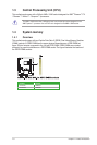
1.2.2 Layout contents
Connectors/Jumpers/Slots/LED Page Connectors/Jumpers/Slots/LED Page
1. ATX power connectors (24-pin EATXPWR, 4-pin ATX12V) 1-13 9. USB connectors (10-1 pin USB56, USB 78, USB910) 1-12
2. AM2 CPU Socket 1-3 10. Clear RTC RAM (3-pin CLRTC) 1-7
3. DDR2 DIMM slots 1-3 11. Internal speaker connector (4-pin SPEAKER) 1-13
4. Keyboard/mouse power (3-pin PS2_USBPW 1-4) 1-9 12. Standby power LED (SB_PWR) 1-1
5. IDE connector (40-1 pin PRI_IDE) 1-11 13. System panel connector (10-1 pin F_PANEL) 1-14
6. CPU fan connector (4-pin CPU_FAN) 1-12 14. Optical drive audio connector (4-pin CD) 1-11
7. Serial ATA connectors (7-pin SATA1, SATA2) 1-10 15. Front panel audio connector (10-1 pin AAFP) 1-14
8. USB device wake-up (3-pin USBPW 5-10) 1-8 16. PCIe x16/PCIe x1/PCI slots 1-7
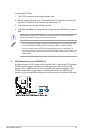
Place this side towards
the rear of the chassis.
1-2ASUS M2N68-AM SE2