


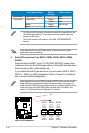
2-20 Chapter 2: Hardware information
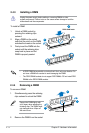
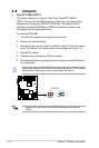
• Pin 20 on the IDE connector is removed to match the covered hole on the
Ultra DMA cable connector. This prevents incorrect insertion when you
connect the IDE cable.
• Use the 80-conductor IDE cable for Ultra DMA
133/100/66/33 IDE
devices.
Drive jumper setting Mode of
device(s)
Cable connector
Single device Cable-Select or Master - Black
Two devices Cable-Select Master
Black
Slave Gray
Master Master Black or gray
Slave Slave
If any device jumper is set as “Cable-Select,” make sure all other device
jumpers have the same setting.
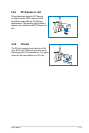
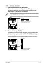
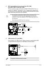
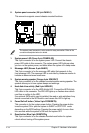
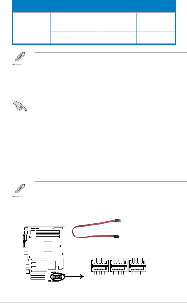
3. Serial ATA connectors (7-pin SATA1, SATA2, SATA3, SATA4, SATA5,
SATA6)
Supported by the NVIDIA
®
nForce
®
570 SLI MCP (MCP55P) chipset, these
connectors are for the Serial ATA signal cables for Serial ATA hard disk drives
that allows up to 3Gb/s of data transfer rate.
If you installed Serial ATA hard disk drives, you can create a RAID 0, RAID 1,
RAID 0+1, RAID 5, or JBOD conguration. Refer to Chapter 5 for details on
how to set up the RAID congurations.
These connectors are set to SATA by default. In SATA mode, you can connect
Serial ATA boot or data hard disk drives to these connectors. If you intent to
create a Serial ATA RAID set using these connectors, enable the RAID function
of each port from the nVIDIA RAID Setup sub-menu item in the BIOS. See
section “4.4.3 Onboard Device Conguration” for details.
M2N-L
®
M2N-L SATA Connectors
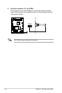
SATA1
GND
RSATA_RXP1
RSATA_RXN1
GND
RSATA
_
TXN1
GND
RSATA_TXP1
SATA2
GND
RSATA_TXP2
RSATA_TXN2
GND
RSATA_
RXN2
RSATA_
RXP2
GND
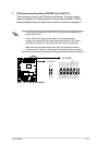
SATA3
GND
RSATA_RXP3
RSATA_RXN3
GND
RSATA
_
TXN3
GND
RSATA_TXP3
SATA4
GND
RSATA_
TXP4
RSATA_
TXN4
GND
RSATA_
RXN4
RSATA_
RXP4
GND
SATA5
GND
RSATA_RXP5
RSATA_RXN5
GND
RSATA
_
TXN5
GND
RSATA_TXP5
SATA6
GND
RSATA_
TXP6
RSATA_
TXN6
GND
RSATA_
RXN6
RSATA_
RXP6
GND