


1-301-30
1-301-30
1-30
Chapter 1: Product introductionChapter 1: Product introduction
Chapter 1: Product introductionChapter 1: Product introduction
Chapter 1: Product introduction
M2NPV-VM
®
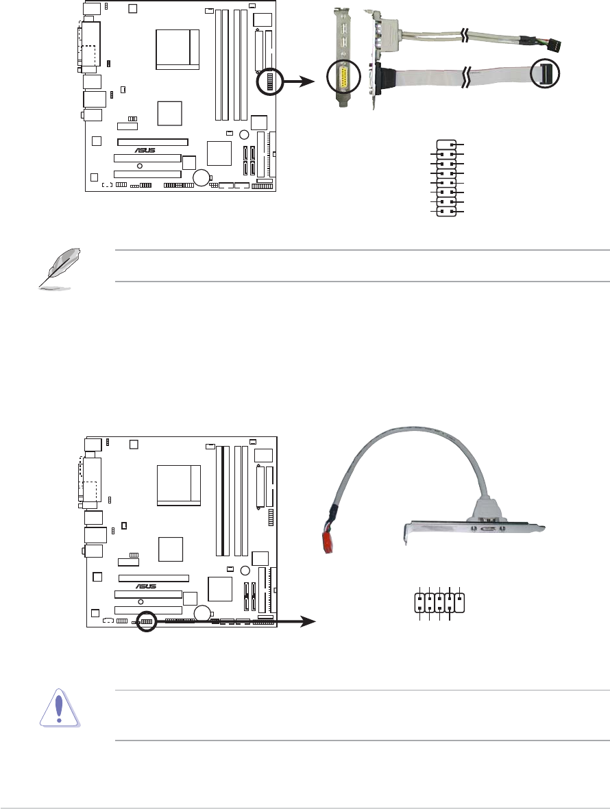
M2NPV-VM IEEE 1394a connector
IE1394_1
1
TPA1-
GND
TPB1-
+12V
GND
TPA1+
GND
TPB1+
+12V
10.10.
10.10.
10.
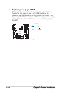
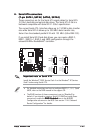
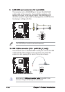
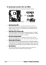
IEEE 1394a connector (10-1 pinIE1394_1 [red])IEEE 1394a connector (10-1 pinIE1394_1 [red])
IEEE 1394a connector (10-1 pinIE1394_1 [red])IEEE 1394a connector (10-1 pinIE1394_1 [red])
IEEE 1394a connector (10-1 pinIE1394_1 [red])
This connector is for an additional IEEE 1394a port. Connect the IEEE
1394a module cable (orange) to this connector, then install the
module to a slot opening at the back of the system chassis.
Never connect a
USB port module cableUSB port module cable
USB port module cableUSB port module cable
USB port module cable to the IEEE 1394a
connector. Doing so will damage the motherboard!
9.9.
9.9.
9.
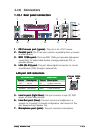
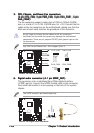
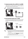
GAME/MIDI port connector (16-1 pin GAME)GAME/MIDI port connector (16-1 pin GAME)
GAME/MIDI port connector (16-1 pin GAME)GAME/MIDI port connector (16-1 pin GAME)
GAME/MIDI port connector (16-1 pin GAME)
This connector is for a GAME/MIDI port. Connect the USB/GAME
module cable to this connector, then install the module to a slot
opening at the back of the system chassis. The GAME/MIDI port
connects a joystick or game pad for playing games, and MIDI devices
for playing or editing audio files.
M2NPV-VM
®
M2NPV-VM GAME connector
GAME
+5V
+5V
J2B1
J2CX
MIDI_OUT
J2CY
J2B2
MIDI_IN
J1B1
J1CX
GND
GND
J1CY
J1B2
+5V
The GAME/MIDI port module is purchased separately.