


ASUS M2NPV-VMASUS M2NPV-VM
ASUS M2NPV-VMASUS M2NPV-VM
ASUS M2NPV-VM
1-311-31
1-311-31
1-31
M2NPV-VM
®
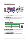
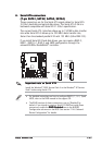
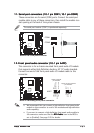
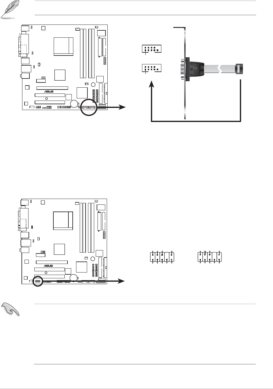
M2NPV-VM COM port connector
PIN 1
COM2
PIN 1
COM1
11.11.
11.11.
11.
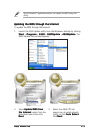
Serial port connectors (10-1 pin COM1; 10-1 pin COM2)Serial port connectors (10-1 pin COM1; 10-1 pin COM2)
Serial port connectors (10-1 pin COM1; 10-1 pin COM2)Serial port connectors (10-1 pin COM1; 10-1 pin COM2)
Serial port connectors (10-1 pin COM1; 10-1 pin COM2)
These connectors are for serial (COM) ports. Connect the serial port
module cable to any of these connectors, then install the module to a
slot opening at the back of the system chassis.
12.12.
12.12.
12.
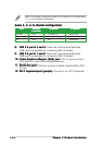
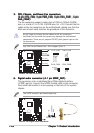
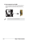
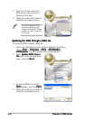
Front panel audio connector (10-1 pin AAFP)Front panel audio connector (10-1 pin AAFP)
Front panel audio connector (10-1 pin AAFP)Front panel audio connector (10-1 pin AAFP)
Front panel audio connector (10-1 pin AAFP)
This connector is for a chassis-mounted front panel audio I/O module
that supports either High Definition Audio or AC`97 audio standard.
Connect one end of the front panel audio I/O module cable to this
connector.
• We recommend that you connect a high-definition front panel audio
module to this connector to avail of the motherboard high-definition
audio capability.
• If you want to connect a high-definition front panel audio module to
this connector, make sure that the
HD Audio HD Audio
HD Audio HD Audio
HD Audio item in the BIOS is
set to [Enabled]. See page 2-28 for details.
M2NPV-VM
®
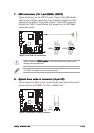
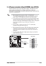
M2NPV-VM Analog front panel connector
AAFP
Azalia-compliant
pin definition
Legacy AC’97-compliant
pin definition
NC
MIC2
Line out_R
Line out_L
NC
NC
MICPWR
NC
AGND
PORT1 R
SENSE2_RETUR
PORT1 L
PORT2 R
PORT2 L
SENSE1_RETUR
SENSE_SEND
PRESENCE#
GND
The serial port bracket (COM1) is purchased separately.