


36 ASUS ME-99 User’s Manual
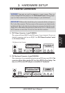
Connectors
3. H/W SETUP
3. HARDWARE SETUP
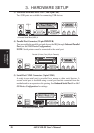
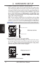
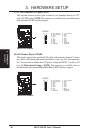
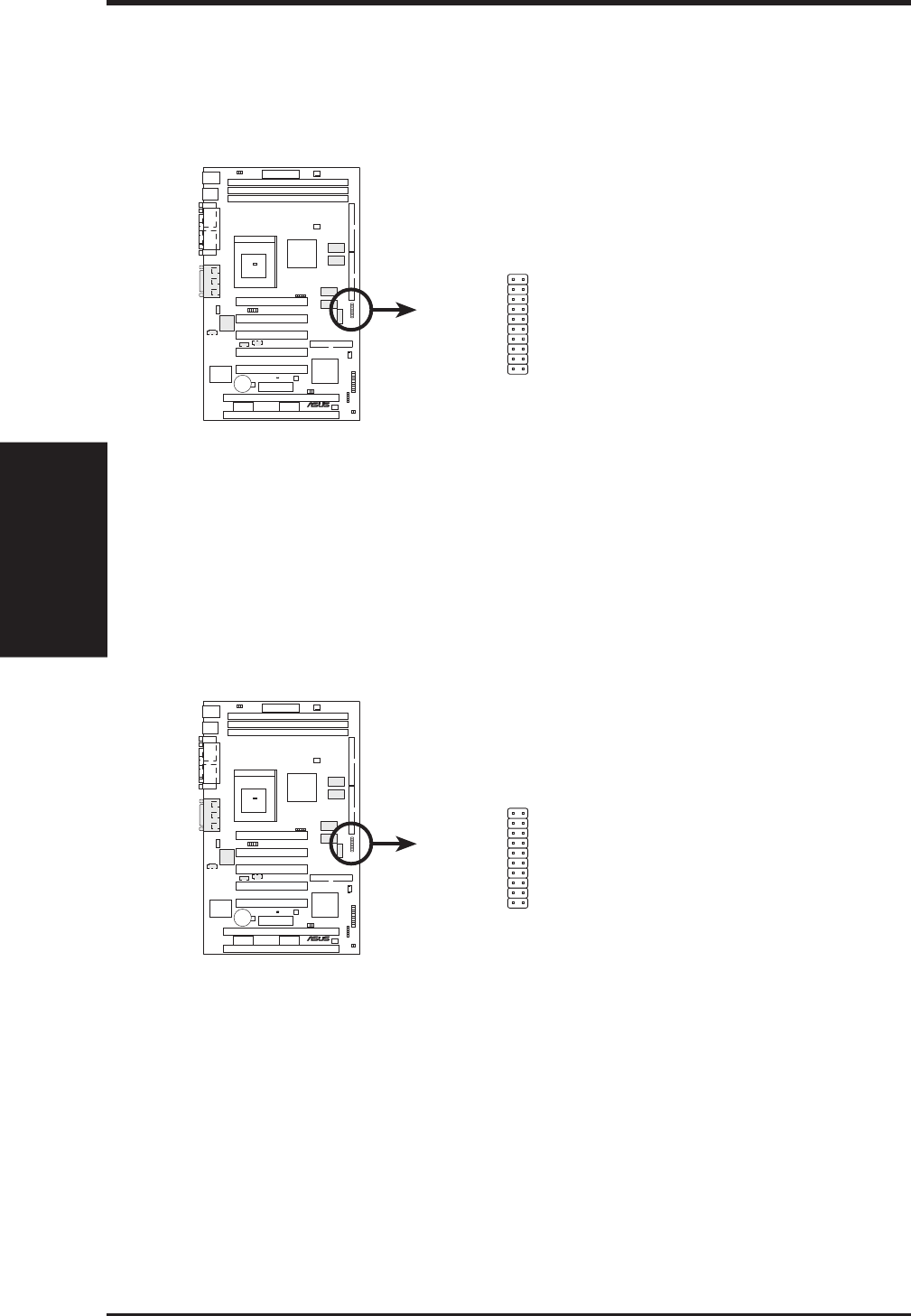
18) LCD Header (20-pin LCDHD)
This header supports the provided LCD cable with mounting bracket. Connect
the cable to this header and mount the bracket to the case on a free expansion
slot. You can make available the LCD port by setting the DSW2-7 switch to ON
(see 3.4 Motherboard Settings). NOTE: This connector is available only on
motherboards with optional Digital Flat Panel (DFP) interface support.
010101
®
ME-99
ME-99 LCD Header
LCDHD
1
11
10
20
20: (No connection)
19: (No connection)
18: TX2+
17: GND
16: TX1-
15: TX0+
14: GND
13: TXC-
12: 0+5V
11: FDDCDAT
10: (No connection)
9: GND
8: TX2-
7: TX1+
6: GND
5: TX0-
4: TXC+
3: GND
2: PLSENSE
1: FDDCCLK
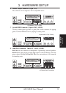
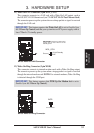
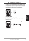
17) TV Out Connector (12-1 pin SCART)
This optional connector allows you to connect your computer directly to a TV
with a SCART socket. NOTE: This connector is available only on motherboards
with optional SCART interface support.
010101
®
ME-99
ME-99 LCD Header
LCDHD
1
11
10
20
20: (No connection)
19: (No connection)
18: TX2+
17: GND
16: TX1-
15: TX0+
14: GND
13: TXC-
12: 0+5V
11: FDDCDAT
10: (No connection)
9: GND
8: TX2-
7: TX1+
6: GND
5: TX0-
4: TXC+
3: GND
2: PLSENSE
1: FDDCCLK