


38 ASUS ME-99 User’s Manual
Connectors
3. H/W SETUP
3. HARDWARE SETUP
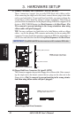
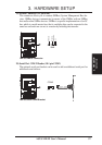
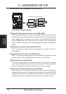
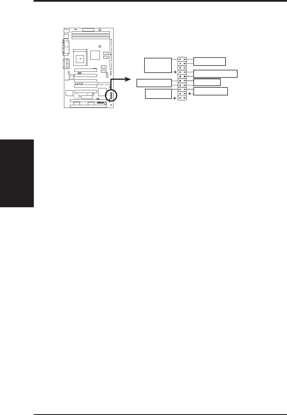
The following PANEL illustration is used for items 21-27
ME-99 System Panel Connectors
*
Requires an ATX power supply.
ATX Power Switch
Reset Switch
Keyboard Lock
Speaker
Connector
Message LED
SMI Lead
Power LED
010101
®
ME-99
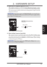
21) System Warning Speaker Connector (4-pin SPEAKER)
This 4-pin connector connects to the case-mounted speaker. You may leave this
disconnected if your motherboard has an onboard buzzer which can replace the
chassis speaker. When connected, you will hear system warnings through both
sources. NOTE: Some sound cards allow you to connect to the system speaker
signal so that the warnings can be heard and adjusted through your multimedia
system.
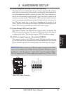
22) Keyboard Lock Switch Lead (2-pin KEYLOCK)
This 2-pin connector connects to the case-mounted key switch to allow key-
board locking.
23) System Power LED Lead (3-1 pin KEYLOCK)
This 3-1 pin connector connects the system power LED, which lights when the
system is powered on and blinks when it is in sleep or soft-off mode.
24) Reset Switch Lead (2-pin RESET)
This 2-pin connector connects to the case-mounted reset switch for rebooting
your computer without having to turn off your power switch. This is a preferred
method of rebooting to prolong the life of the system’s power supply.
25) ATX Power / Soft-Off Switch Lead (2-pin PWRSW)
The system power is controlled by a momentary switch connected to this lead.
Pressing the button once will switch the system between ON and SOFT OFF.
Pushing the switch while in the ON mode for more than 4 seconds will turn the
system off. The system power LED shows the status of the system’s power.