


28 ASUS MES-VM User’s Manual
Connectors
3. H/W SETUP
3. HARDWARE SETUP
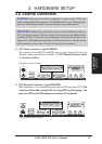
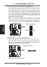
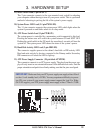
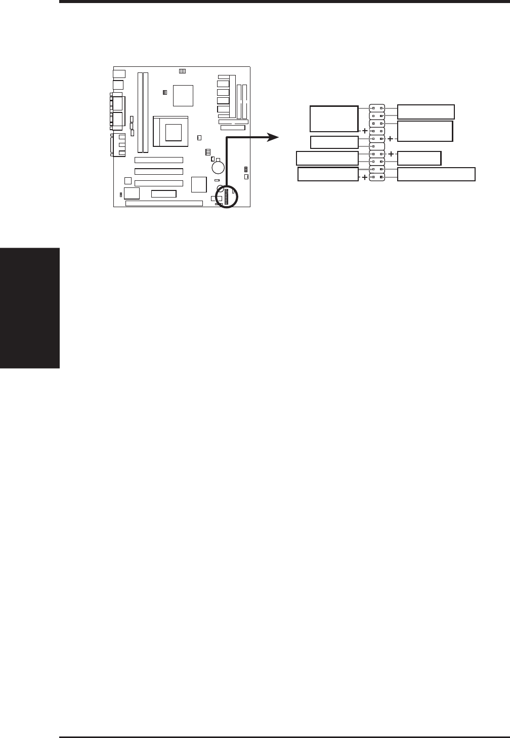
The following PANEL illustration is used for items 16-23
MES-VM System Panel Connectors
SMI Lead
ATX Power Switch
Reset Switch
Keyboard Lock
IDELED
Speaker
Connector
Message LED
Power LED
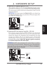
15) System Warning Speaker Connector (4-pin SPEAKER)
This 4-pin connector connects to the case-mounted speaker. You may leave this
disconnected if your motherboard has an onboard buzzer which can replace the
chassis speaker. When connected, you will hear system warnings through both
sources. NOTE: Some sound cards allow you to connect to the system speaker
signal so that the warnings can be heard and adjusted through your multimedia
system.
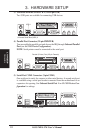
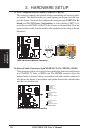
16) System Management Interrupt Lead (2-pin SMI)
This allows the user to manually place the system into a suspend mode or “Green”
mode, where system activity is decreased to save electricity and expand the life
of certain components when the system is not in use. This 2-pin connector con-
nects to the case-mounted suspend switch. If you do not have a switch for the
connector, you may use the “Turbo Switch.” SMI is activated when it detects a
short to open moment and therefore leaving it shorted will not cause any prob-
lems. This may require one or two presses depending on the position of the
switch. Wake-up can be controlled by settings in the BIOS but the keyboard will
always allow wake-up (the SMI lead cannot wake up the system).
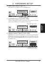
17) Keyboard Lock Switch Lead (2-pin KEYLOCK)
This 2-pin connector connects to the case-mounted key switch to allow key-
board locking.
18) Message LED Lead (2-pin MSG.LED)
This indicates whether a message has been received from a fax/modem. The
LED will remain lit when there is no signal and blink when there is data transfer
or waiting in the inbox. This function requires ACPI OS and driver support.