


1-6
Chapter 1: Product introduction
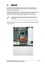
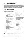
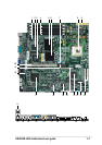
1.3 Motherboard overview
Before you install the NR-LSR motherboard, familiarize yourself with its
physical configuration and available features to facilitate the motherboard
installation and future upgrades. A sufficient knowledge of the motherboard
specifications will also help you avoid mistakes that may damage the
board and its components.
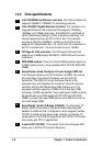
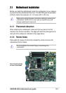
1.3.1 Major components
The following are the major components of the NR-LSR motherboard as
pointed out in the picture on page 1-7.
1. Intel
®
82550PM Fast Ethernet
controller
2. Intel
®
82544GC Gigabit Ethernet
controller
3. ATI Rage-XL VGA controller
4. DDR DIMM sockets
5. ServerWorks
®
Grand Champion
LE North Bridge (CMIC-LE)
6. ServerWorks
®
64-bit I/O Bridge
(CIOB-X2)
7. 5-switch DIP (CLKSW)
8. CPU Socket 478
9. 24/20-pin ATX power connector
10. Backplane bridge board
connectors
11. Flash ROM
12. 8-switch DIP (U78)
13. ServerWorks
®
Champion South
Bridge (CSB5)
14. Server Management
daughterboard connectors
15. LPC super I/O controller
16. ASUS ASIC
17. LSI
®
SCSI controller
18. Ultra-160 SCSI connector
(internal)
19. PCI extended power connector
20. 64-bit 133/100MHz PCI slot
21. PS/2 mouse port
22. PS/2 keyboard port
23. RJ-45 port (100/10 Mbps)
24. RJ-45 port (1000/100/10 Mbps)
25. Serial port
26. RJ-45 port (for server
management)
27. VGA port
28. SCSI LED
29. High-density SCSI connector
30. USB 1.1 ports
31. Location switch
32. Location LED
See page 1-8 for the specifications of each component. Refer to
Chapter 2 for detailed information on the components.