


ASUS NR-LSR motherboard user guide
2-15
2.8 Connectors
This section describes and illustrates the internal connectors on the
motherboard.
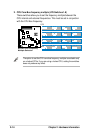
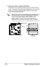
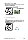
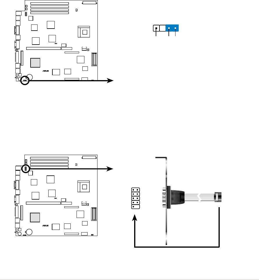
2. Serial port 2 connector (10-1 pin COM2)
This connector accommodates a second serial port using an optional
serial port bracket. Connect the bracket cable to this connector then
install the bracket into a slot opening at the back of the system chassis.
NR-LSR
®
NR-LSR Chassis Open Alarm Lead
U79
+5Volt
(Power Supply Stand By)
Chassis Signal
Ground
NR-LSR
®
1
NR-LSR Serial COM2 Connector
COM2
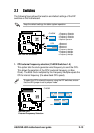
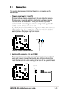
1. Chassis alarm lead (4-1 pin U79)
This lead is for a chassis designed with intrusion detection feature.
This requires an external detection mechanism such as a chassis
intrusion sensor or microswitch. When you remove any chassis
component, the sensor triggers and sends a high-level signal to this
lead to record a chassis intrusion event.
By default, the pins labeled “Chassis Signal” and “Ground” are shorted
with a jumper cap. If you wish to use the chassis intrusion detection
feature, remove the jumper cap from the pins.