


64 ASUS P2B-L/P2B-S/P2B-LS User’s Manual
LED Connectors
Link Indicator: This connects to an LED to monitor 10Base-T and 100Base-TX con-
nections. The LED lights to indicate a successful network connection, and remains steady
if the connection is stable. If this indicator is off, the cable connection between the hub
and the computer may be faulty or the driver configuration may be faulty.
Activity Indicator: This connects to an LED to monitor network activity. The LED
lights when there are network packets sent or received through the RJ45 port. The rate
of flashing is proportional to the amount of network traffic. If this is off, the computer
is not sending or receiving network data.
Speed Indicator: This connects to an LED to monitor connection speed. The LED
lights (On) when connection is made to a 100Base-TX host. If Off, the network
connection is operating at 10Mbps.
Network Cable Connection
Twisted Pair Ethernet (TPE) - Connect a single network cable to the RJ45 connector.
For 100BASE-TX, your network cable must be category 5 (not category 3), twisted-
pair wiring with RJ45 connectors. If you plan on running the interface at 100 Mbps, it
must be connected to a 100BASE-TX hub (not a 100BASE-T4 hub). For 10BASE-T,
use category 3, 4, or 5 twisted-pair wiring.
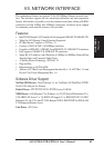
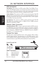
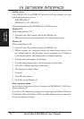
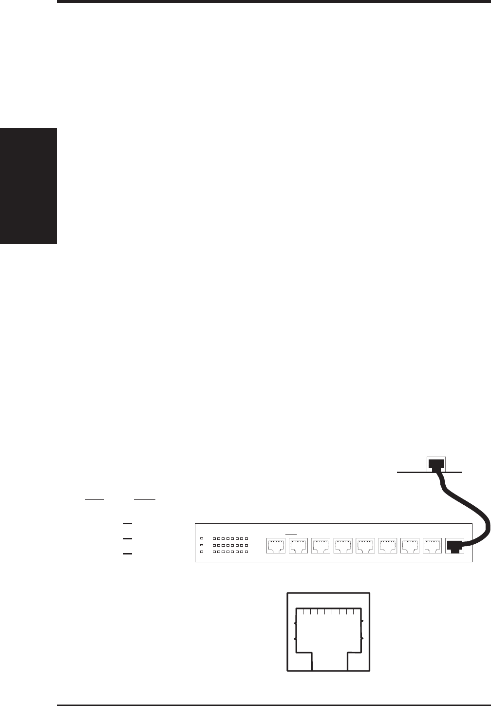
Twisted-Pair Cable
The cable used to connect the Ethernet card to a host (generally a Hub) is called a
straight-through twisted-pair. The end connectors are called RJ45 connectors, which
are not compatible with the standard RJ11 telephone connectors. The illustration shows
a connection between a typical Hub and this motherboard’s network interface.
VII. NETWORK
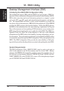
Layout/Installation
VII. NETWORK INTERFACE
1Uplink 2345678
12345678 12345678 1234567812345678123456781234567812345678 12345678 12345678
RJ45
HUB
Motherboard
Straight-Through Cable
Hub Card
1 IRD+ 1 OTD+
2 IRD- 2 OTD-
3 OTD+ 3 IRD+
6 OTD- 6 IRD-
18234567
HUB RJ45 Connector
RJ45 Connector
Pin 1 Output Transmit Data +
Pin 2 Output Transmit Data -
Pin 3 Input Receive Data +
Pin 6 Input Receive Data -
Pins 4,5,7,8 (Reserved)