


ASUS P3W User’s Manual 39
3. HARDWARE SETUP
Connectors
3. H/W SETUP
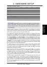
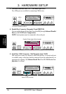
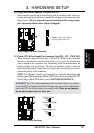
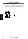
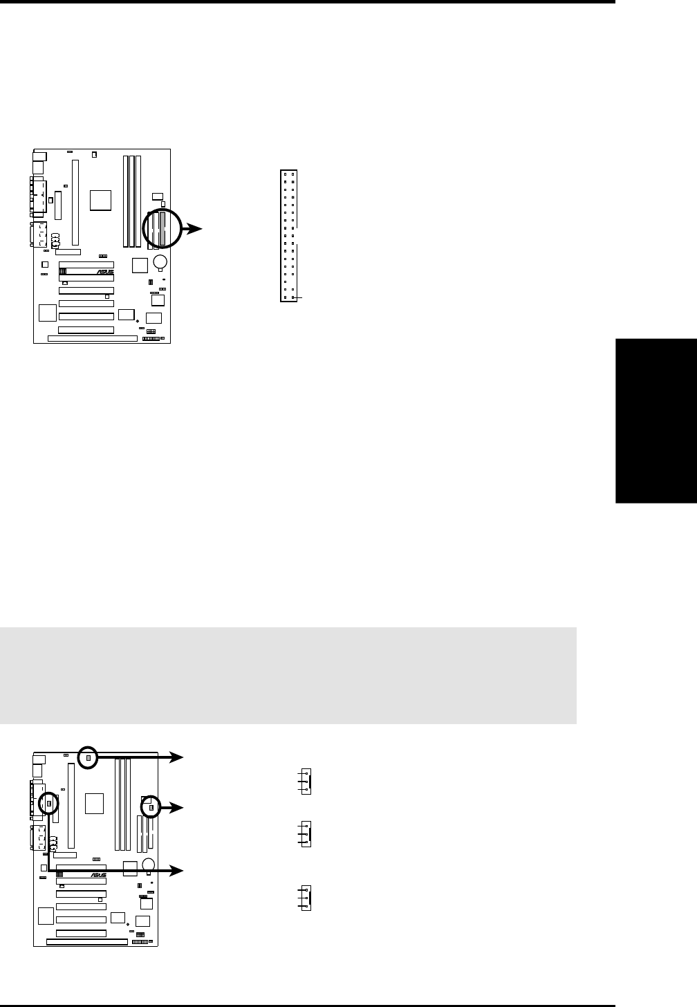
11) Floppy Disk Drive Connector (34-1pin FLOPPY)
This connector supports the provided floppy disk drive ribbon cable. After con-
necting the single end to the board, connect the two plugs on the other end to the
floppy drives. (Pin 5 is removed to prevent inserting in the wrong orienta-
tion when using ribbon cables with pin 5 plugged).
NOTE: Orient the red markings on
the floppy ribbon cable to
PIN 1
P3W Floppy Disk Drive Connector
PIN 1
10101
®
P3W
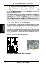
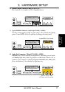
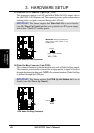
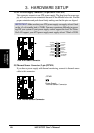
12) Chassis, CPU, & Power Supply Fan Connectors (3-pin CHA_, CPU_, PWR_FAN)
These connectors support cooling fans of 350mA (4.2 Watts) or less. Orientate
the fans so that the heat sink fins allow airflow to go across the onboard heat
sink(s) instead of the expansion slots. Depending on the fan manufacturer, the
wiring and plug may be different. The red wire should be positive, while the
black should be ground. Connect the fan’s plug to the board taking into consid-
eration the polarity of the connector.
NOTE: The “Rotation” signal is to be used only by a specially designed fan with
rotation signal. The Rotations per Minute (RPM) can be monitored using ASUS PC
Probe Utility or Intel LDCM Utility (see 6. SOFTWARE REFERENCE).
WARNING! The CPU and/or motherboard will overheat if there is no airflow
across the CPU and onboard heatsinks. Damage may occur to the motherboard
and/or the CPU fan if these pins are incorrectly used. These are not jumpers,
do not place jumper caps over these pins.
10101
®
P3W
P3W 12-Volt Cooling Fan Power
Chassis Fan Power
GND
Rotation
+12V
Power Supply Fan
CPU Fan Power
GND
Rotation
+12V
GND
Rotation
+12V