


ASUS P3W User’s Manual 45
3. HARDWARE SETUP
Connectors
3. H/W SETUP
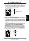
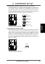
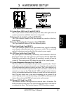
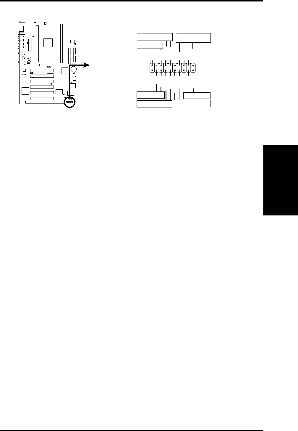
The following PANEL illustration is used for items 22-28
10101
®
P3W
P3W System Panel Connectors
*
Requires an ATX power supply.
Keyboard Lock
PLED
Ground
MLED
PWR_SW
+5 V
Keylock
+5V
SPKR
Ground
+5 V
ExtSMI#
ResetCon
Ground
Ground
Ground
Reset SW
Power LED
ATX Power Switch*
Message LED
SMI Lead
Speaker
Connector
Ground
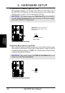
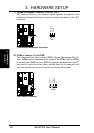
22) System Power LED Lead (3-1 pin KEYLOCK)
This 3-1 pin connector connects the system power LED, which lights when the
system is powered on and blinks when it is in sleep mode.
23) Keyboard Lock Switch Lead (2-pin KEYLOCK)
This 2-pin connector connects to the case-mounted key switch to allow key-
board locking.
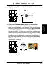
24) System Warning Speaker Connector (4-pin SPEAKER)
This 4-pin connector connects to the case-mounted speaker.
25) Reset Switch Lead (2-pin RESET)
This 2-pin connector connects to the case-mounted reset switch for rebooting
your computer without having to turn off your power switch. This is a preferred
method of rebooting to prolong the life of the system’s power supply.
26) ATX Power Switch Lead (2-pin PWR)
The system power is controlled by a momentary switch connected to this lead.
Pressing the button once will switch the system between ON and SOFT OFF.
Pushing the switch while in the ON mode for more than 4 seconds will turn the
system off. The system power LED shows the status of the system’s power.
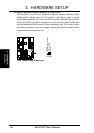
27) System Management Interrupt Lead (2-pin SMI)
This allows the user to manually place the system into a suspend mode or “Green”
mode, where system activity is decreased to save electricity and expand the life
of certain components when the system is not in use. This 2-pin connector con-
nects to the case-mounted suspend switch. If you do not have a switch for the
connector, you may use the “Turbo Switch.” SMI is activated when it detects a
short to open moment and therefore leaving it shorted will not cause any prob-
lems. This may require one or two presses depending on the position of the
switch. Wake-up can be controlled by settings in the BIOS but the keyboard will
always allow wake-up (the SMI lead cannot wake up the system).
28) Message LED Lead (2-pin LED)
This indicates whether a message has been received from a fax/modem. The
LED will remain lit when there is no signal and blink when there is data transfer
or waiting in the inbox. This function requires ACPI OS and driver support.