


ASUS P4B533-V motherboard user guide
2-31
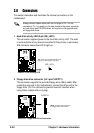
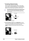
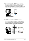
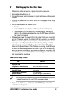
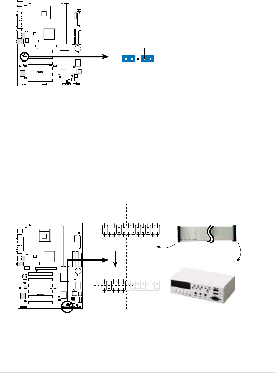
14. Line in connector (5-pin FP_LINE_IN1)
(on audio models only)
This connector is for a front panel Line In jack with a return path for
automatic signal switching. By default, pins 1-2 and pins 5-6 are
shorted with jumper caps to make the Line In source available from the
rear panel Line In jack. Remove the jumper caps if you desire to install
the Intel front panel audio cable.
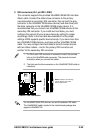
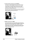
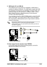
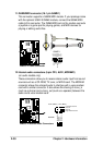
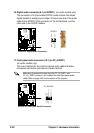
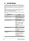
15. ASUS iPanel connector (24-1 pin AFPANEL1)
(optional)
This connector allows you to connect an optional ASUS iPanel, an
easy-to-access drive bay with front I/O ports and status LEDs. If you
are not using an ASUS iPanel, you can connect an optional wireless
transmitting and receiving infrared module to the SIR connector.
P4B533-V
®
P4B533-V LINE_IN Connector
FP_LINE1
AGND
BLINE_LIN_L
ALINE_LIN_L
BLINE_IN_R
LINE_IN_R
P4B533-V
®
P4B533-V iPanel Connector
+5VSB
NC
CHASSIS#
+5 V
PCIRST#
GND
CIRRX
EXTSMI#
MLED-
NC
BATT
NC
SMBDATA
GND
+3VSB
IRRX
IRTX
NC
NC
NC
+5V SMBCLK
NC
+5VSB
NC
+5 V
GND
CIRRX
NC
GND
IRRX
IRTX
CIR
SIR
IR_CON
AFPANEL1
Connect to iPanel
Connect to AFPANEL Connector