


2-2
Chapter 2: Hardware information
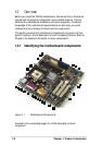
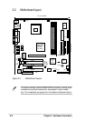
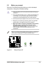
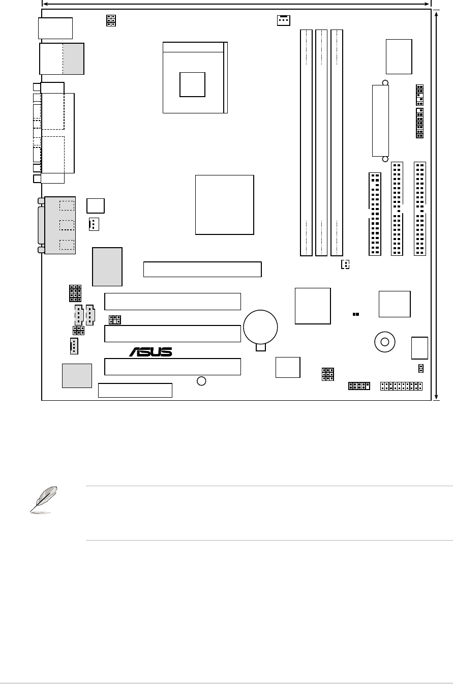
2.2 Motherboard layout
Figure 2-2 Motherboard Layout
®
PS/2KBMS
T: Mouse
B: Keyboard
PANEL
FLOPPY
SECONDARY IDE
PRIMARY IDE
Intel I/O
Controller
Hub
(ICH2)
P4B-M
CR2032 3V
Lithium Cell
CMOS Power
ATX Power Connector
2Mbit
Firmware
Hub
ATX12V
Intel 845
Memory
Controller
Hub (MCH)
AUX
CPU_FAN
DIP_SW
USB23
CD
BUZZER
LED1
COM1
PARALLEL PORT
COM2
MODEM
DIMM Socket 1 (64/72-bit, 168-pin module)
0 1
DIMM Socket 2 (64/72-bit, 168-pin module)
2 3
DIMM Socket 3 (64/72-bit, 168-pin module)
4 5
GAME_AUDIO
Mic
In
Line
Out
Line
In
SYSTEM_FAN
HDDLED
24.4cm (9.60in)
24.4cm (9.6in)
CNR_SLOT
C-Media
CMI8738 6CH
Audio Controller
Super
I/O
Realtek
RTL8100
ASUS
ASIC
SPDIF_C
USBPWR23
CNRUSB0
CNRUSB1
IR_CON
KBPWR USBPWR01
BCS2
BCS1
LAN_EN
HPHONE
MIC
INT_LINEIN
SMARTCON
SERIRQ_CON
Socket 478
Accelerated Graphics Port (AGP)
PCI1
PCI2
PCI3
USB1
USB2
Bottom:
RJ-45
Top:
CLEAR CMOS
The audio controller, external GAME/AUDIO connectors, internal audio
connectors are optional components, and present in audio models
only. The components are grayed out in the above motherboard layout.