


2-30
Chapter 2: Hardware information
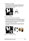
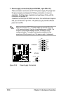
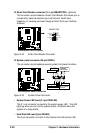
15. System panel connector (20-pin PANEL)
This connector accommodates several system front panel functions.
Figure 2-43 System Panel Connector
• System Power LED Lead (3-1 pin PWR.LED)
This 3-1 pin connector connects to the system power LED. The LED
lights up when you turn on the system power, and blinks when the
system is in sleep mode.
• Hard Disk LED Lead (2-pin IDELED)
This 2-pin connector connects to the chassis hard disk activity LED.
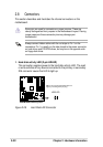
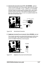
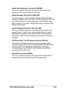
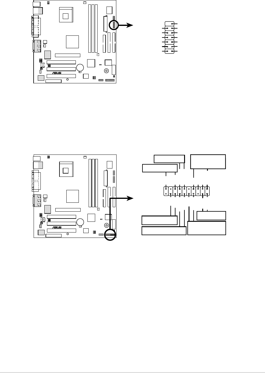
Figure 2-42 Smart Card Reader Connector
14. Smart Card Reader connector (14-1 pin SMARTCON)
(optional)
This connector accommodates a Smart Card Reader that allows you to
conveniently make transactions such as financial, health care,
telephony, or traveling services through a Smart Card user interface
software.
®
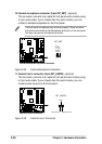
P4B-M
P4B-M Smart Card Connector
SMARTCON
NC
SCRFET#
LED
RFU2
NC2
VCC
GND
SCRUI
SCRRES#
NC
SCRCLK
1
RFU1
SCRREST
®
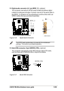
P4B-M
P4B-M System Panel Connectors
*
Requires an ATX power supply.
PLED
Ground
MLED
PWR
+5 V
IDELED+
+5V
Speaker
Speaker
Connector
Power LED
Ground
+5 V
Reset SW
SMI Lead
Message LED
ExtSMI#
Ground
Reset
Ground
Ground
IDELED-
IDELED
ATX Power
Switch*