


2-24
Chapter 2: Hardware information
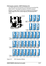
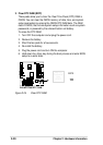
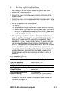
Figure 2-29 USB Header
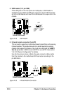
5. USB header (10-1 pin USB)
If the USB ports on the rear panel are inadequate, a USB header is
available for two additional USB ports. Connect a 2-port USB connector
set to the USB header and mount the USB bracket to an open slot in the
chassis.
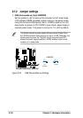
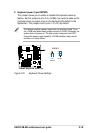
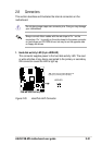
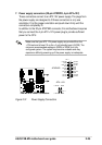
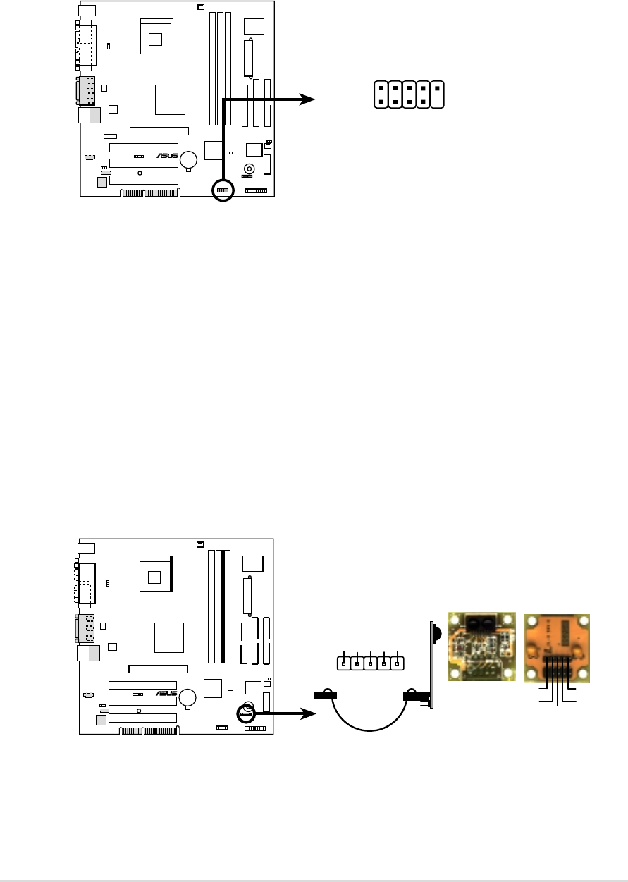
6. Infrared module connector (5-pin IR)
This connector supports an optional wireless transmitting and receiving
infrared module. This module mounts to a small opening on system
chassis that support this feature. You must also configure the UART2
Use As parameter in BIOS to set UART2 for use with IR. See section
“4.4.2 I/O Device Configuration” for details.
Use the five pins as shown in Back View and connect a ribbon cable
from the module to the motherboard SIR connector according to the
pin definitions..
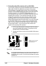
Figure 2-30 Infrared Module Connector
®
P4B-MX
Front View Back View
+5V
IRTX
IRRX
(NC)
GND
+5V
IRRX
IRTX
(NC)
GND
IR
1
P4B-MX Infrared Module Connector
®
P4B-MX
USB
1
5
6
10
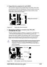
P4B-MX USB Header
1: USB Power
2: USBP2–
3: USBP2+
4: GND
5: NC
6: USB Power
7: USBP3–
8: USBP3+
9: GND