


1-24
Chapter 1: Product introduction
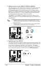
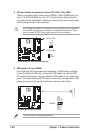
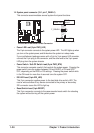
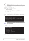
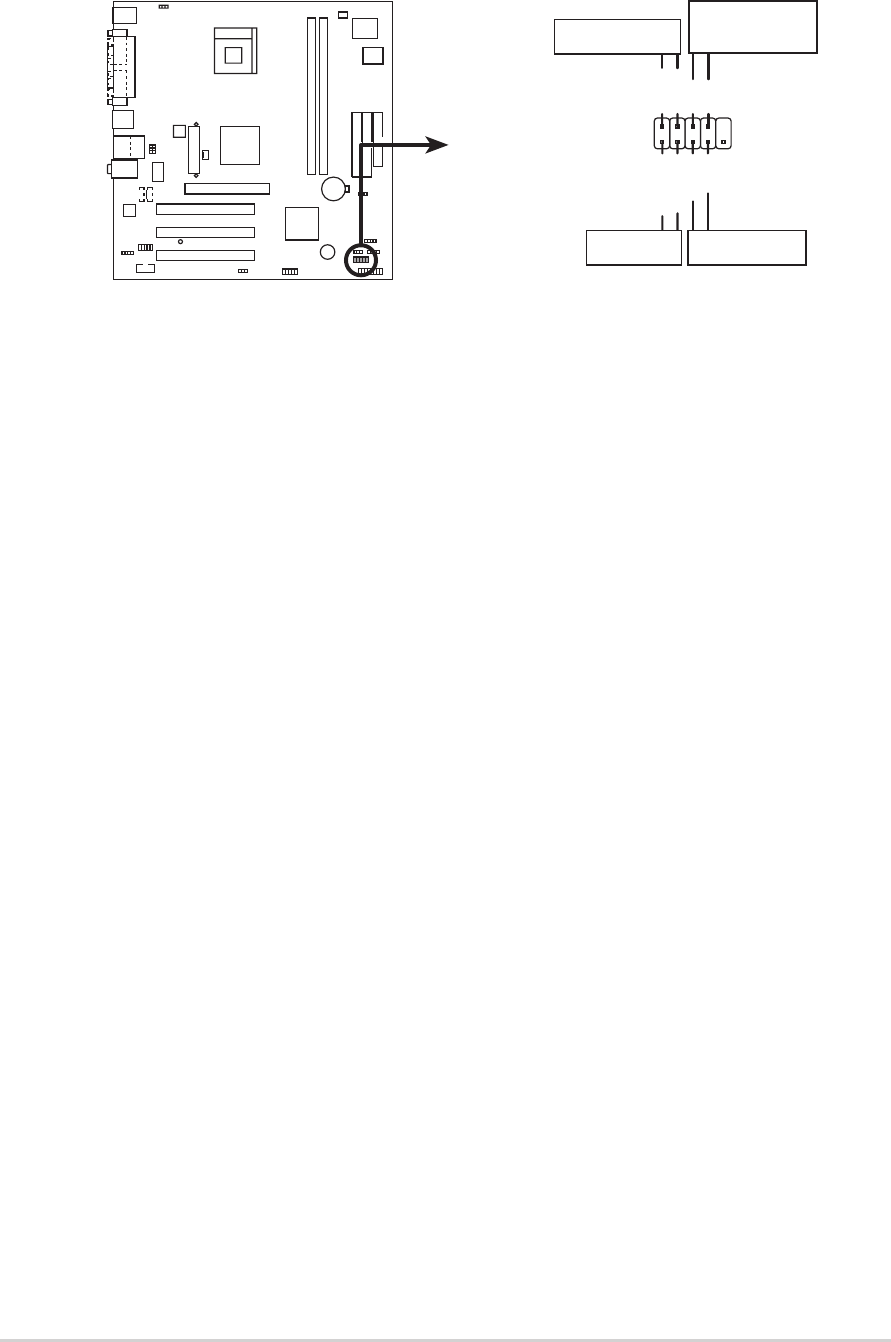
14. System panel connector (10-1 pin F_PANEL1)
This connector accommodates several system front panel functions.
• Power LED Lead (2-pin PWR_LED)
This 2-pin connector connects to the system power LED. The LED lights up when
you turn on the system power, and blinks when the system is in sleep mode.
If your motherboard package comes with a 2-pin to 3-pin power LED converter,
connect the 2-pin plug to this connector, and the other end to the 3-pin power
LED plug from the system chassis.
• Power Switch / Soft-Off Switch Lead (2-pin PWR_BTN)
This connector connects a switch that controls the system power. Pressing the
power switch turns the system between ON and SLEEP, or ON and SOFT
OFF, depending on the BIOS or OS settings. Pressing the power switch while
in the ON mode for more than 4 seconds turns the system OFF.
• IDE LED Lead (2-pin IDE_LED)
This 2-pin connector supplies power to the hard disk drive activity LED. The
read or write activities of any device connected to the primary or secondary
IDE connector cause this LED to light up.
• Reset Switch Lead (2-pin RESET)
This 2-pin connector connects to the case-mounted reset switch for rebooting
the system without turning off the system power.
P4S800-MX
P4S800-MX Front Panel Audio Connector
F_PANEL1
PLED-
PWR
PLED+
Ground
GNDReset
IDE_LED+
IDE_LED-
Power LED
Reset SW
ATX Power
Switch*
IDE_LED
* Requires an ATX power supply
.