ASUS P5E3 Deluxe/WiFi-AP @n 2-31
• For a fully congured system, we recommend that you use a power supply
unit (PSU) that complies with ATX 12 V Specication 2.0 (or later version)
and provides a minimum power of 400 W.
• Do not forget to connect the 8-pin / 4-pin EATX12V power plug; otherwise,
the system will not boot.
• Use of a PSU with a higher power output is recommended when
conguring a system with more power-consuming devices. The system
may become unstable or may not boot up if the power is inadequate.
• If you want to use two high-end PCI Express x16 cards, use a PSU with
500W to 600W power or above to ensure the system stability.
• If you are uncertain about the minimum power supply requirement for your
system, refer to the Recommended Power Supply Wattage Calculator
at http://support.asus.com/PowerSupplyCalculator/PSCalculator.
aspx?SLanguage=en-us for details.
• The ATX 12 V Specication 2.0-compliant (400W) PSU has been tested
to support the motherboard power requirements with the following
conguration:
CPU: Intel
®
Pentium
®
Extreme 3.73GHz
Memory: 512 MB DDR3 (x4)
Graphics card: ASUS EAX1900XT
Parallel ATA device: IDE hard disk drive
Serial ATA device: SATA hard disk drive (x2)
Optical drive: DVD-RW
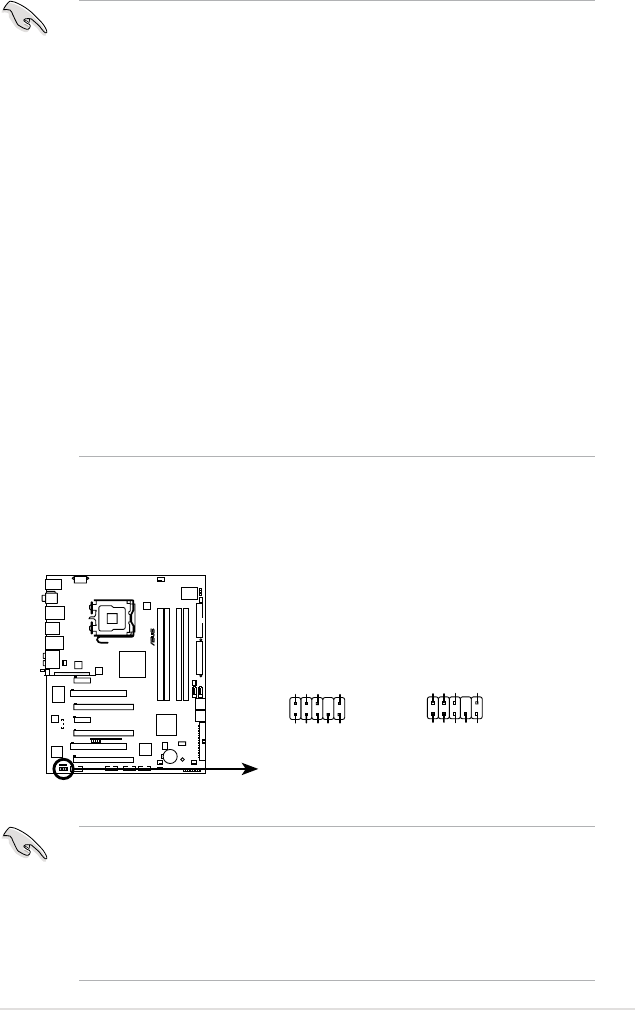
9. Front panel audio connector (10-1 pin AAFP)
This connector is for a chassis-mounted front panel audio I/O module that
supports either HD Audio or legacy AC`97 audio standard. Connect one end
of the front panel audio I/O module cable to this connector.
•
We recommend that you connect a high-denition front panel audio
module to this connector to avail of the motherboard’s high-denition audio
capability.
•
If you want to connect a high-denition front panel audio module to this
connector, make sure that the Front Panel Type item in the BIOS is set to
[HD Audio]. If you want to connect an AC' 97 front panel audio module to
this connector, set the item to [AC97]. Refer to page 4-26 or details.
P5E3 DELUXE
®
P5E3 DELUXE/WiFi-AP
Analog front panel connector
AAFP
Legacy AC ‘97 audio
pin definition
SENSE2_RETUR
PORT1 L
PORT2 R
PORT2 L
SENSE1_RETUR
SENSE_SEND
PORT1 RPRESENCE#
GND
NC
MIC2
Line out_R
Line out_L
NC
NC
MICPWRNC
AGND
HD Audio-compliant
pin definition


