


ASUS P5GDC ProASUS P5GDC Pro
ASUS P5GDC ProASUS P5GDC Pro
ASUS P5GDC Pro
2-52-5
2-52-5
2-5
Internal connectorsInternal connectors
Internal connectorsInternal connectors
Internal connectors
PagePage
PagePage
Page
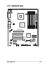
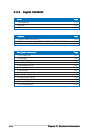
1. Floppy disk drive connector (34-1 pin FLOPPY) 2-29
2. Primary IDE connector (40-1 pin PRI_IDE) 2-30
3. Serial ATA connectors (7-pin SATA1, SATA2, SATA3, SATA4) 2-31
4. CPU fan connector (4-pin CPU_FAN) 2-32
5. Chassis fan connectors (3-pin CHA_FAN1, CHA_FAN2) 2-32
6. Power fan connector (3-pin PWR_FAN) 2-32
7. Serial port connector (10-1 pin COM1) 2-33
8. USB connectors (10-1 USB56, USB78) 2-33
9. ATX power connector (24-pin EATXPWR) 2-34
10. ATX 12V power connector (4-pin ATX12V) 2-34
11. Optical drive audio connector (4-pin CD) 2-35
12. GAME/MIDI connector (16-1 pin GAME) 2-35
13. Chassis intrusion connector (4-1 pin CHASSIS1) 2-36
14. Front panel audio connector (10-1 pin AAFP) 2-37
15. System panel connectors (20 pin PANEL) 2-38
- System Power LED (Green 3-pin PLED)
- Hard Disk activity (Red 2-pin IDE_LED)
- System warning speaker (Orange 4-pin SPEAKER)
- Power/Soft-off button(Yellow 2-pin PWRSW)
- Reset switch (Blue 2-pin RESET)