


1-28 Chapter 1: Product introduction
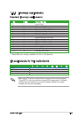
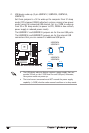
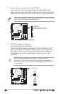
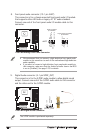
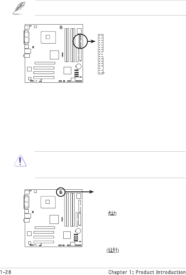
2. Floppy disk drive connector (34-1 pin FLOPPY)
This connector is for the provided Floppy Disk Drive (FDD) signal
cable. Insert one end of the cable to this connector, then connect the
other end to the signal connector at the back of the floppy disk drive.
Pin 5 on the connector is removed to prevent incorrect cable connection
when using an FDD cable with a covered Pin 5.
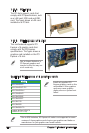
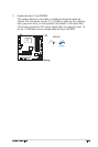
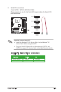
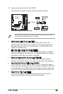
3. CPU and chassis fan connectors
(4-pin CPU_FAN, 3-pin CHA_FAN)
The fan connectors support cooling fans of 350mA~2000mA (24W
max.) or a total of 1A~3.48A (41.36W max.) at +12V. Connect the
fan cables to the fan connectors on the motherboard, making sure
that the black wire of each cable matches the ground pin of the
connector.
Do not forget to connect the fan cables to the fan connectors.
Insufficient air flow inside the system may damage the motherboard
components. These are not jumpers! DO NOT place jumper caps on the
fan connectors.
P5GV-MX
®
NOTE: Orient the red markings on
the floppy ribbon cable to PIN 1.
P5GV-MX Floppy Disk Drive Connector
PIN 1
FLOPPY
P5GV-MX
®
P5GV-MX Fan Connectors
CPU_FAN
CHA_FAN
GND
CPU FAN PWR
CPU FAN IN
CPU FAN PWM
GND
Rotation
+12V
1
1