


1-30
Chapter 1: Product introduction
1.10.2 Internal connectors
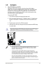
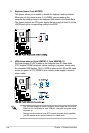
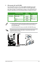
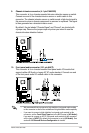
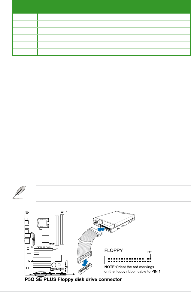
1. Floppy disk drive connector (34-1 pin FLOPPY)
This connector is for the provided oppy disk drive (FDD) signal cable. Insert
one end of the cable to this connector, then connect the other end to the
signal connector at the back of the oppy disk drive.
Pin 5 on the connector is removed to prevent incorrect cable connection when
using a FDD cable with a covered Pin 5.
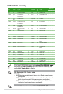
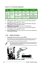
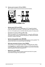
Audio 2, 4, 6, or 8-channel conguration
Port
Headset
2-channel
4-channel 6-channel 8-channel
Light Blue Line In Line In Line In Line In
Lime Line Out Front Speaker Out Front Speaker Out Front Speaker Out
Pink Mic In Mic In Mic In Mic In
Orange – – Center/Subwoofer Center/Subwoofer
Black – Rear Speaker Out Rear Speaker Ou Rear Speaker Out
Gray – – – Side Speaker Out
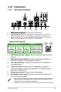
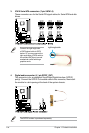
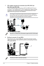
9. USB 2.0 ports 1 and 2. These two 4-pin Universal Serial Bus (USB) ports
are available for connecting USB 2.0 devices.
10. USB 2.0 ports 3 and 4. These two 4-pin Universal Serial Bus (USB) ports
are available for connecting USB 2.0 devices.
11. PS/2 keyboard port (purple)PS/2 keyboard port (purple). This port is for a PS/2 keyboard.
12. USB 2.0 ports 5 and 6. These two 4-pin Universal Serial Bus (USB) ports
are available for connecting USB 2.0 devices.
13. Optical S/PDIF Out port. This port connects an external audio output device
via a optical S/PDIF cable.