


ASUS P5RD2-VM 1-29
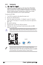
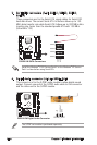
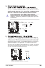
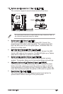
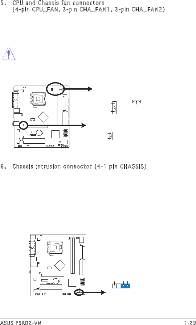
5. CPU and Chassis fan connectors
(4-pin CPU_FAN, 3-pin CHA_FAN1, 3-pin CHA_FAN2)
The fan connectors support cooling fans of 350mA~740mA (8.88W
max.) or a total of 1A~2.22A (26.64W max.) at +12V. Connect the fan
cables to the fan connectors on the motherboard, making sure that the
black wire of each cable matches the ground pin of the connector.
Do not forget to connect the fan cables to the fan connectors.
Insufficient air flow inside the system may damage the motherboard
components. These are not jumpers! DO NOT place jumper caps on the
fan connectors.
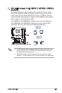
P5RD2-VM Fan Connectors
CHA_FAN2
GND
Rotation
+12V
CHA_FAN1
GND
Rotation
+12V
CPU_FAN
GND
CPUFANPWR
CPUFANIN
CPUFANPWM
®
P5RD2-VM
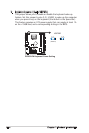
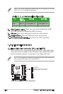
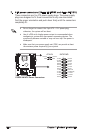
6. Chassis intrusion connector (4-1 pin CHASSIS)
This connector is for a chassis-mounted intrusion detection sensor or
switch. Connect one end of the chassis intrusion sensor or switch cable
to this connector. The chassis intrusion sensor or switch sends a high-
level signal to this connector when a chassis component is removed or
replaced. The signal is then generated as a chassis intrusion event.
By default, the pins labeled “Chassis Signal” and “Ground” are shorted
with a jumper cap. Remove the jumper caps only when you intend to
use the chassis intrusion detection feature.
®
P5RD2-VM
P5RD2-VM Chassis Intrusion Connector
CHASSIS
(Default)
+5VSB_MB
Chassis Signal
GND