


1-28
Chapter 1: Hardware information
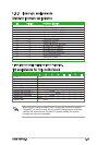
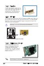
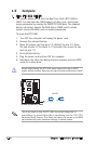
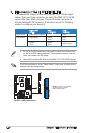
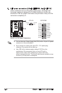
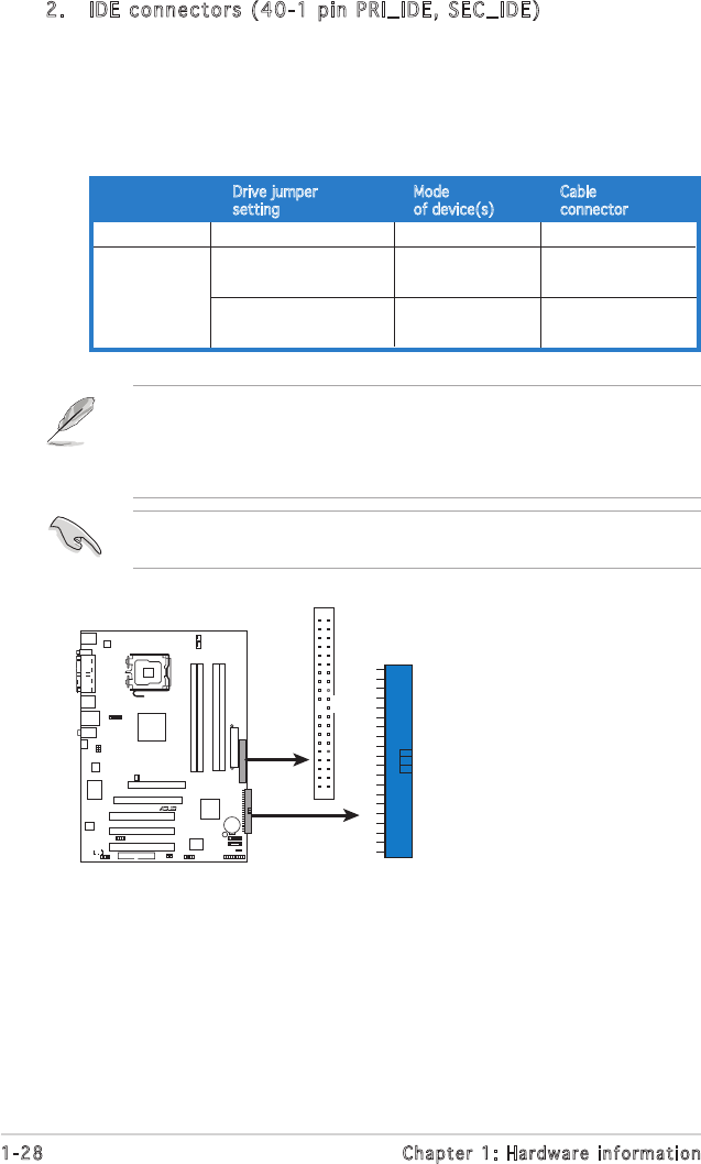
2. IDE connectors (40-1 pin PRI_IDE, SEC_IDE)
The onboard IDE connectors are for Ultra DMA 133/100/66 signal
cables. There are three connectors on each Ultra DMA 133/100/66
signal cable: blue, black, and gray. Connect the blue connector to
the motherboardʼs IDE connector, then select one of the following
modes to configure your device(s).
• Pin 20 on the IDE connector is removed to match the covered hole
on the Ultra DMA cable connector. This prevents incorrect insertion
when you connect the IDE cable.
• Use the 80-conductor IDE cable for Ultra DMA 133/100/66 IDE devices.
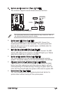
Black or gray
Drive jumper Mode Cable
setting of device(s) connector
Single device Cable-Select or Master - Black
Two devices Cable-Select Master Black
Slave Gray
Master Master
Slave Slave
If any device jumper is set as “Cable-Select,” make sure all other device
jumpers have the same setting.
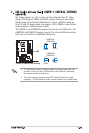
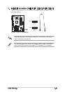
Below:Mic In
Center:Line Out
Top:Line In
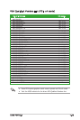
P5VDC-X
R
NOTE: Orient the red markings
(usually zigzag) on the ID
ribbon cable to PIN 1.
P5VDC-X IDE Connectors
SEC_IDE
PRI_IDE