


ASUS P5V-VM Ultra Motherboard 1-27
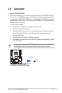
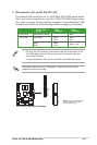
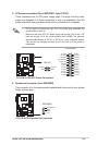
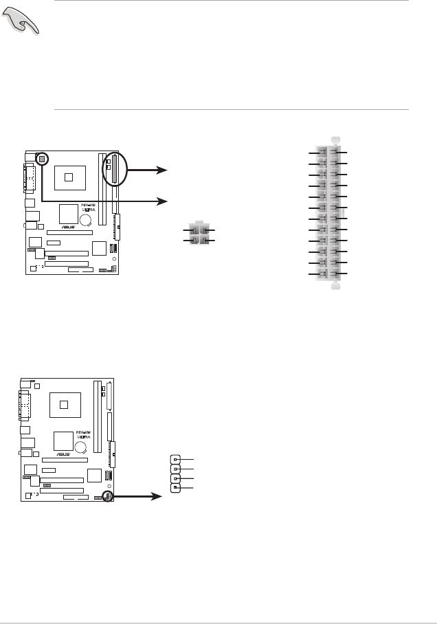
5. ATX power connectors (24-pin EATXPWR, 4-pin ATX12V)
These connectors are for ATX power supply plugs. The plugs from the power
supply are designed to t these connectors in only one orientation. Find the
proper orientation and push down rmly until the connectors t completely.
• Do not forget to connect the 4-pin ATX +12V power plug; otherwise, the
system does not boot up.
• Make sure that your ATX 12V power supply can provide 12A on the +12V
lead and at least 1A on the +5-volt standby lead (+5VSB). The minimum
recommended wattage is 300 W, or 350 W for a fully congured system.
The system can become unstable or will not boot up if the power is
inadequate.
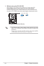
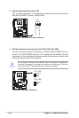
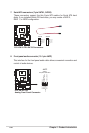
6. Speaker out connector (4-pin SPEAKER)
This connector is for the case-mounted speaker and allows you to hear system
beeps and warnings.
P5V-VM
ULTRA
P5V-VM ULTRA ATX Power Connectors
ATX12V
+12V DC
GND
+12V DC
GND
EATXPWR
+3 Volts
+3 Volts
Ground
+5 Volts
+5 Volts
Ground
Ground
Power OK
+5V Standby
+12 Volts
-5 Volts
+5 Volts
+3 Volts
-12 Volts
Ground
Ground
Ground
PSON#
Ground
+5 Volts
+12 Volts
+3 Volts
+5 Volts
Ground
P5V-VM
ULTRA
P5V-VM ULTRA Speaker Out Connector
SPEAKER
+5V
GND
GND
Speaker Out
1